Magnetic resonance imaging system
a magnetic resonance imaging and magnetic field technology, applied in the field of magnetic resonance imaging system, can solve the problems of insufficient shortening of measurement time, limiting the amount of rf applied or the like, and the switching speed of a gradient magnetic field and the like, so as to shorten the measurement time, suppress artifacts, and high-speed imaging
- Summary
- Abstract
- Description
- Claims
- Application Information
AI Technical Summary
Benefits of technology
Problems solved by technology
Method used
Image

Examples
first embodiment
[0049]Hereinafter, preferred embodiments for implementing the present invention will be explained. A first embodiment to which the present invention is applied will be explained first. This embodiment scans a plurality of linear crossing areas (lines) simultaneously. Hereinafter, a case where two lines are scanned simultaneously will be explained as an example.
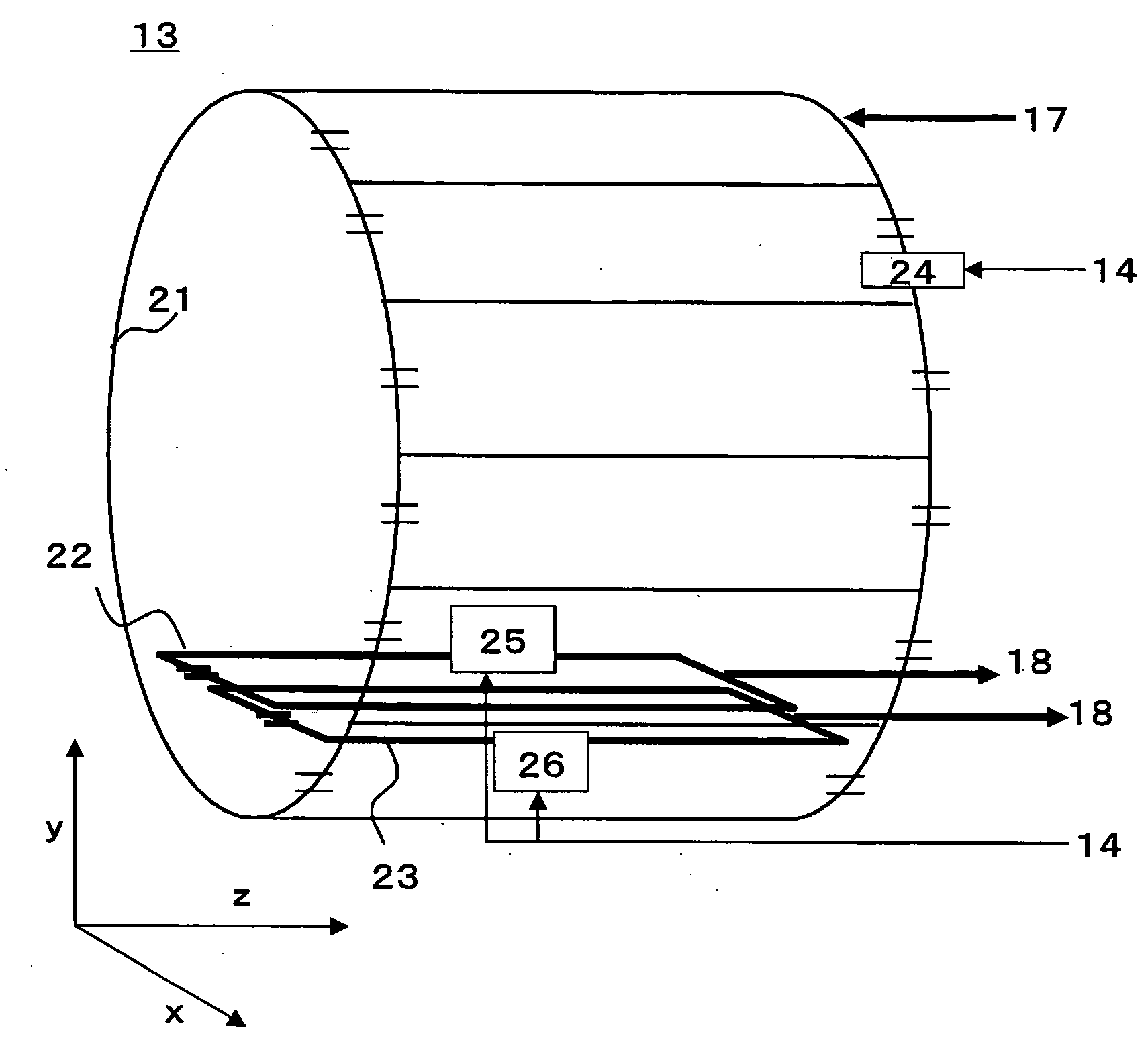
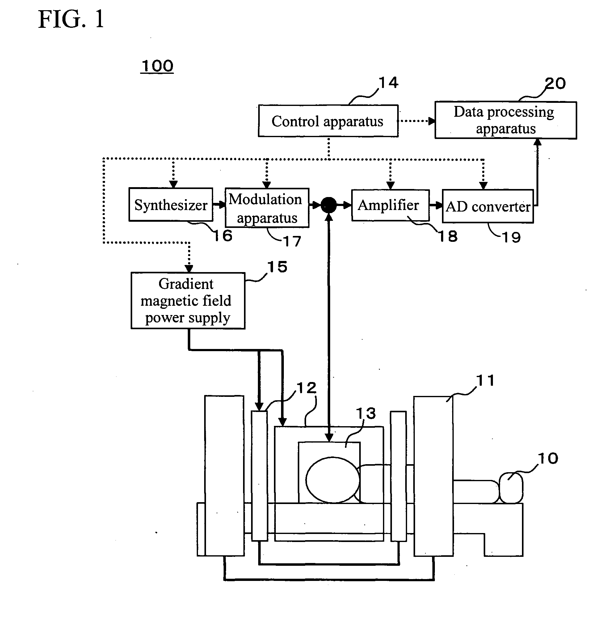
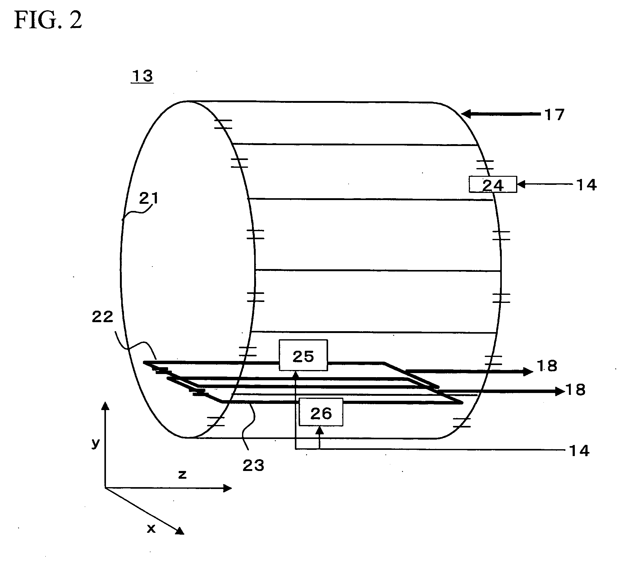
[0050]First, the apparatus configuration of a magnetic resonance imaging system of this embodiment will be explained. FIG. 1 illustrates an overview of a magnetic resonance imaging system 100 of this embodiment. The magnetic resonance imaging system 100 is provided with a static magnetic field generation magnet 11, a gradient magnetic field generation coil 12, an RF coil system 13, a control apparatus 14, a gradient magnetic field power supply 15, a synthesizer 16, a modulation apparatus 17, an amplifier 18, an AD converter 19 and a data processing apparatus 20.
[0051]The synthesizer 16 and the modulation apparatus 17 constitut...
second embodiment
[0087]Next, a second embodiment will be explained. The MRI system of this embodiment basically has a configuration similar to that of the first embodiment. The first embodiment separates both signals using sensitivity distributions of the RF coils 22 and 23 every time measurement of the crossing areas 44 and 45 of the measuring object is completed and acquires a one-dimensional image of each crossing area. On the other hand, this embodiment saves the measurement result of each linear area in a memory or the like, separates images after completing measurement of the whole area of the measuring object and obtains a whole image. Furthermore, this embodiment acquires sensitivity distributions of the RF coils 22 and 23 during measurement of crossing areas 44 and 45. Hereinafter, details of this embodiment will be explained focusing on the configuration different from that of the first embodiment.
[0088]First, a technique of acquiring a sensitivity distribution according to this embodiment...
third embodiment
[0101]Next, a third embodiment will be explained. The MRI system of this embodiment basically has a configuration similar to that of the first embodiment. The first embodiment changes the frequency fn of the first excitation pulse and moves the crossing area to be excited by the second excitation pulse in the slice plane. This embodiment changes the frequency fn of the first excitation pulse and moves the crossing area out of the excitation plane to be excited by the second excitation pulse applied immediately before. Hereinafter, details of this embodiment will be explained focusing on the configuration different from that of the first embodiment.
[0102]First, a method of acquiring echoes by the RF pulse application section, signal detection section, gradient magnetic field application section of this embodiment and the echoes acquired will be explained. In this embodiment, the control apparatus 14 also controls these sections according to programmed timings (imaging pulse sequence)...
PUM
 Abstract
Description
Claims
Application Information