Terminal Box for Solar Cell Module

a solar cell module and terminal box technology, applied in the direction of electrical apparatus casings/cabinets/drawers, pv power plants, substation/switching arrangement casings, etc., can solve the problem of generating undue strain, and achieve the effect of reducing the number of parts, avoiding the concentration of strain on the rectifying element, and improving assembly operability

Inactive Publication Date: 2009-04-02
SUMITOMO WIRING SYST LTD
View PDF8 Cites 25 Cited by
  • Summary
  • Abstract
  • Description
  • Claims
  • Application Information

AI Technical Summary

Benefits of technology

[0014]Since the respective terminal boards are bridged by the rectifying element, an undue strain might act on the rectifying element to affect a rectifying function if an attempt is made to fix the respective terminal boards to the base plate with the rectifying element connected with the terminal boards beforehand. However, according to the present invention, the relative positions of the respective terminal boards can be substantially immovably kept upon fixing the terminal boards to the base plate and the concentration of the strain on the rectifying element can be avoided since the retaining plate for collectively fixing the terminal boards juxtaposed on the top surface of the base plate by sandwiching them is provided.
[0015]Further, by using the retaining plate, the respective terminal boards can be aligned in a flat manner by a relatively simple method, thereby improving assembling operability. By increasing the pressing force of the retaining plate against the terminal boards, the terminal boards can be more closely held in contact with the base plate. Therefore, upon the heat generation of the rectifying element, heat can be efficiently radiated from the terminal boards to the base plate.

Problems solved by technology

Thus, there has been a possibility that an undue strain is generated in a connecting part of the bypass diode and the terminal board and the bypass diode is deformed or disconnected from the terminal board.

Method used


Image

  • Terminal Box for Solar Cell Module
  • Terminal Box for Solar Cell Module
  • Terminal Box for Solar Cell Module

Examples


Embodiment Construction

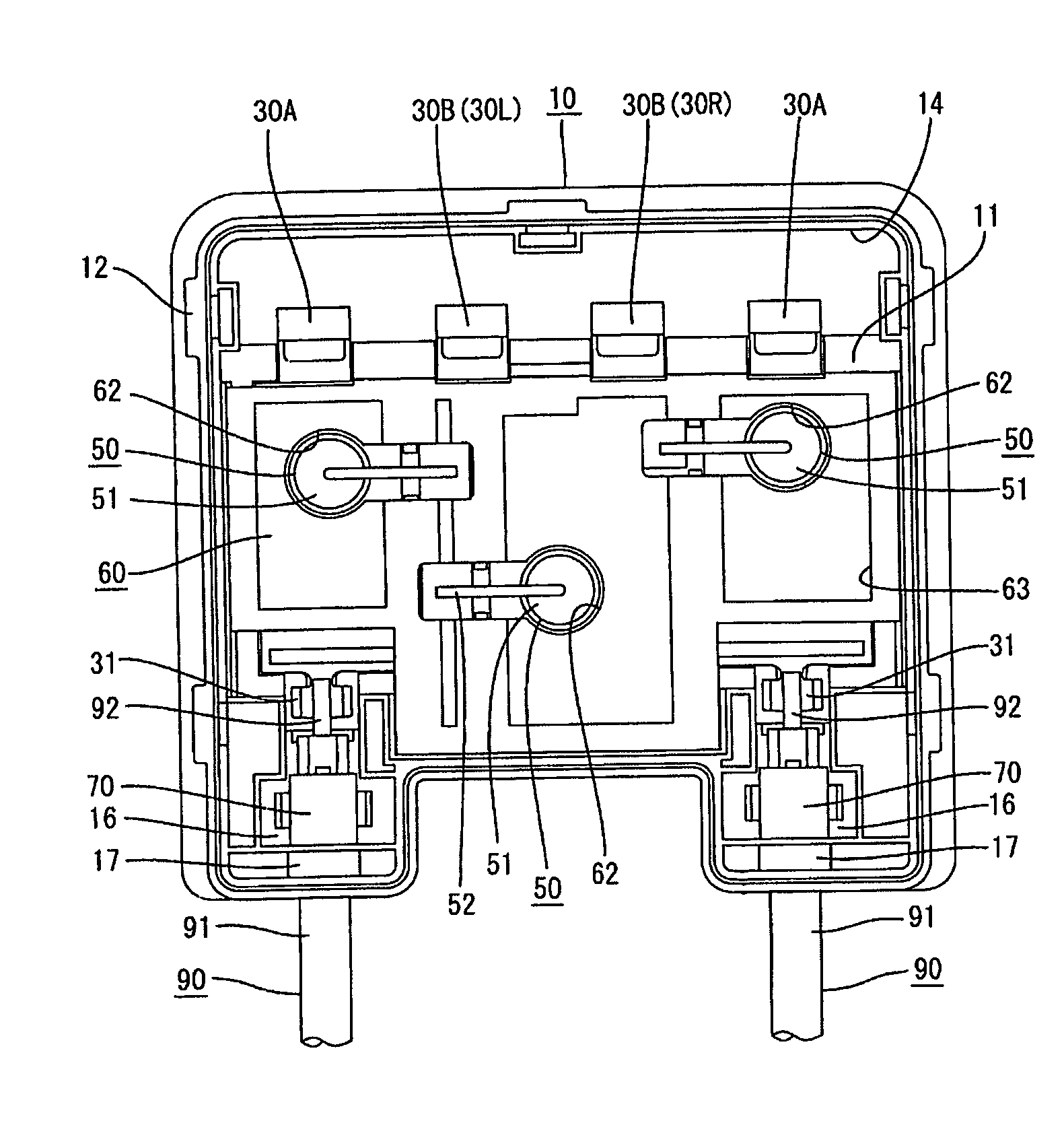
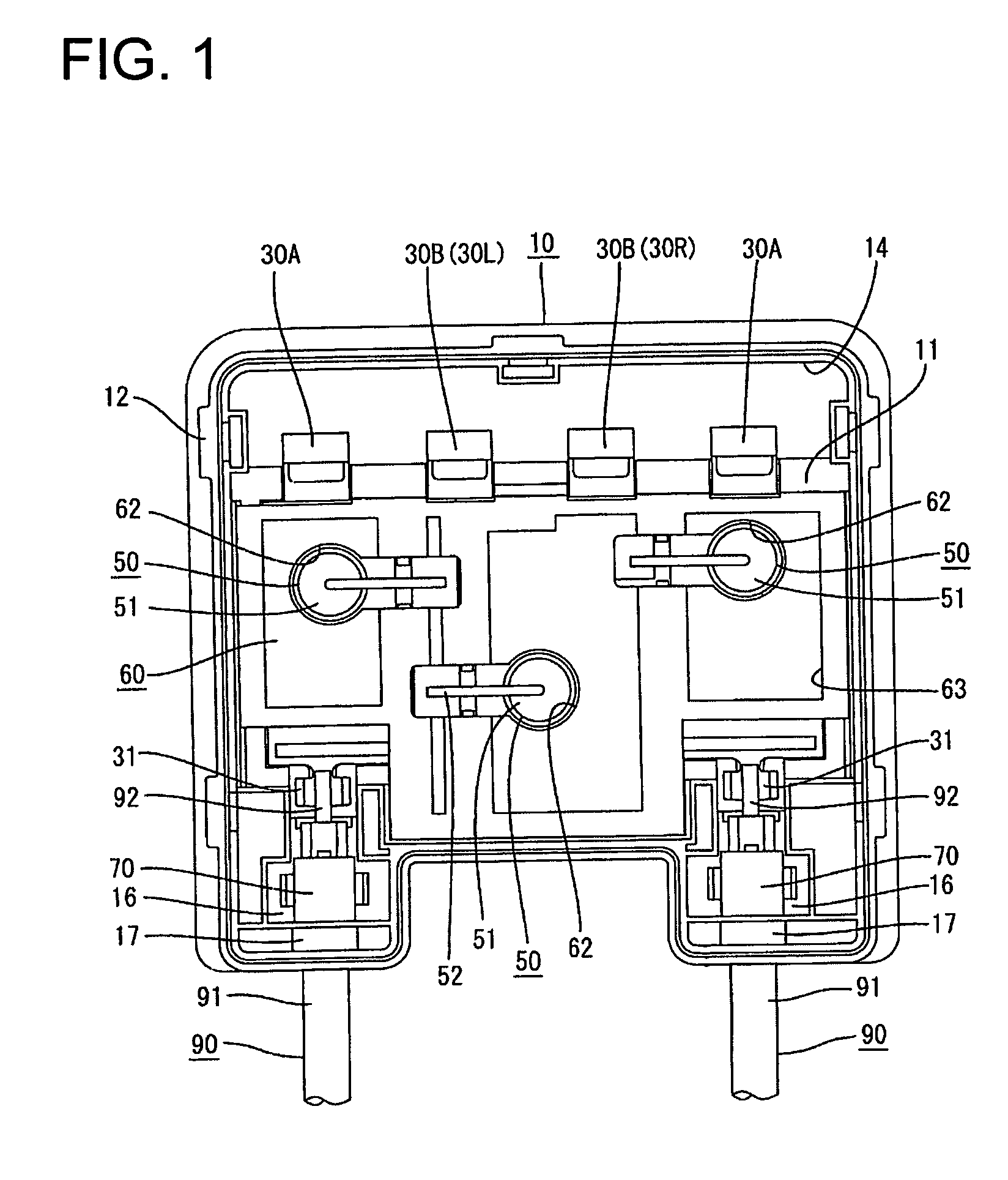
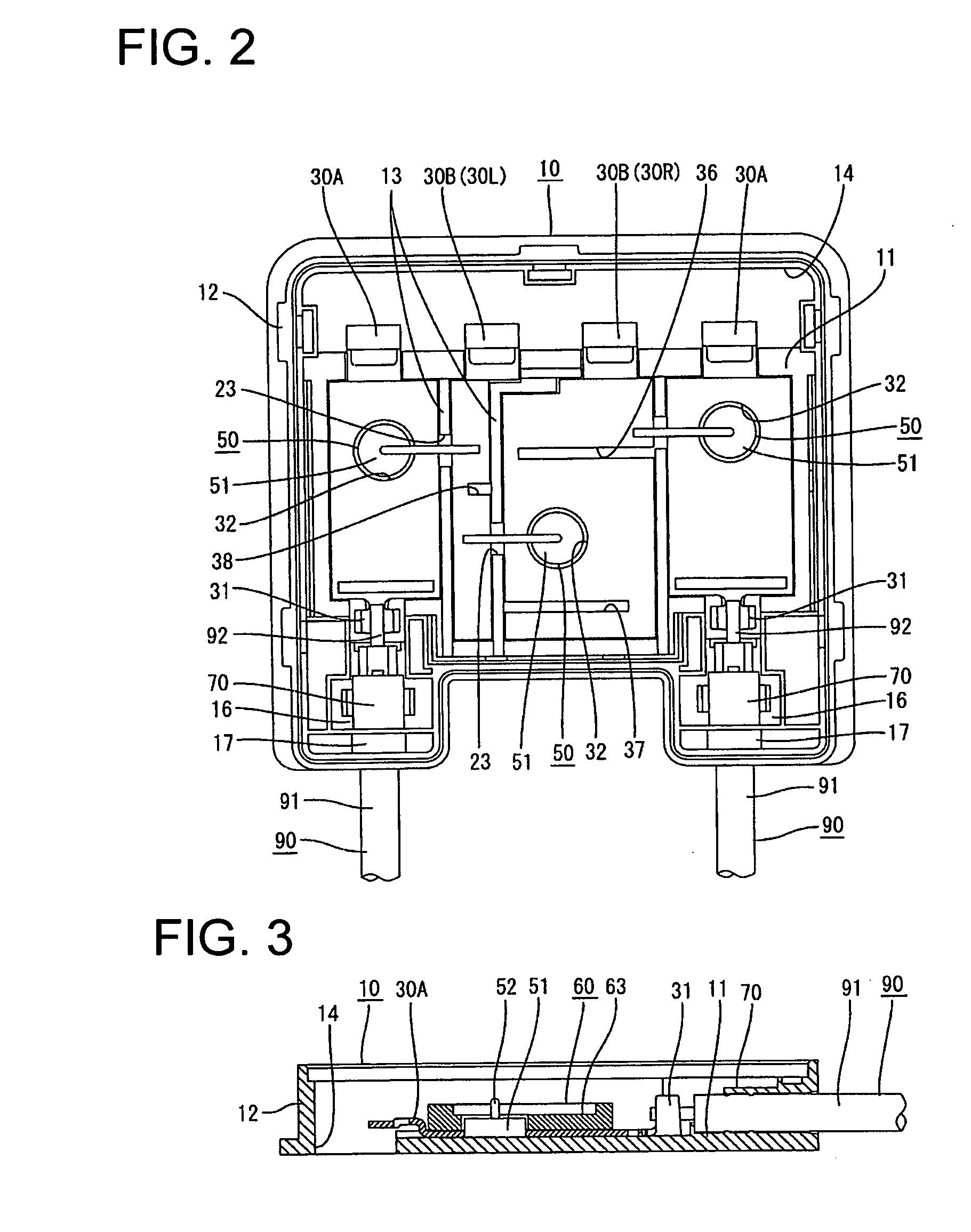
[0022]One embodiment of the invention is described with reference to FIGS. 1 to 6. A terminal box for solar cell module of this embodiment is mounted on the underside of a solar cell module having a multitude of solar battery cells connected with each other in series, and provided with a box-shaped box main body 10, a multitude of terminal boards 30A, 30B arranged in parallel in this box main body 10 and a plurality of bypass diodes 50 (corresponding to a “bypass rectifying element at the time of a reverse load” of the present invention) bridging the adjacent terminal boards 30A, 30B.

[0023]The box main body 10 is made of synthetic resin and has a box shape with an open upper side. An insulating resin material (potting material) is introduced into the box main body 10 and a cover (not shown) is mounted from above. More specifically, as shown in FIGS. 1 and 2, the box main body 10 includes a substantially rectangular base plate 11 on which a plurality of terminal boards 30A, 30B are p...


PUM


Abstract

A plurality of terminal boards (30A, 30B) for electrically interconnecting a plus electrode and a minus electrode of a solar cell module and cables (90) for external connection corresponding to the both electrodes are placed on a base plate (11), and two corresponding terminal boards (30A, 30B) are bridged by a bypass diode (50). The respective terminal boards (30A, 30B) juxtaposed on the top surface of the base plate (11) are collectively supported and fixed by a retaining plate (60). Accordingly, the generation of an undue strain in the bypass diode (50) can be avoided even in the case of fixing the terminal boards (30A, 30B) to the base plate (11) with the terminal boards (30A, 30B) bridged by the bypass diode (50) beforehand.

Description

BACKGROUND OF THE INVENTION[0001]1. Field of the Invention[0002]The present invention relates to a terminal box for solar cell module.[0003]2. Description of the Related Art[0004]A solar photovoltaic system is so constructed as to supply direct currents from a solar cell panel laid on the roof of a house or building to electrical goods via an inverter or the like. The solar cell panel is comprised of a plurality of solar cell modules, and electrodes of the respective solar cell modules are connected in series or in parallel via terminal boxes.[0005]A known terminal box is such that a pair of terminal boards are juxtaposed on a base plate forming the bottom of a box main body, a plus electrode and a minus electrode drawn from the underside of the solar cell module are connected with one ends of the both terminal boards, and ends of cables for external connection are connected with the other ends of the both terminal boards (see, for example, Japanese Patent No. 348945). A bypass diod...

Claims


Application Information

Patent Timeline
Patent Type & Authority Applications(United States)
IPC IPC(8): H05K5/00
CPCH02S40/34H02G3/16Y02E10/50
Inventor YOSHIKAWA, HIROYUKIHIGASHIKOZONO, MAKOTO
Owner SUMITOMO WIRING SYST LTD
Why Eureka
Try Eureka