Substrate processing apparatus

a processing apparatus and substrate technology, applied in the direction of electrical apparatus, conveyor parts, thin material processing, etc., can solve the problem of excessively high speed and difficult stable substrate transport, and achieve the effect of reducing the time required for substrate transpor

Inactive Publication Date: 2009-04-02
DAINIPPON SCREEN MTG CO LTD
View PDF5 Cites 12 Cited by
  • Summary
  • Abstract
  • Description
  • Claims
  • Application Information

AI Technical Summary

Benefits of technology

[0012]In this configuration, the holder is placed on each of the plurality of second placement parts around the substrate transfer part; and the substrate transfer part, without moving in a horizontal direction, takes a substrate out of the holder to transfer the substrate to the substrate transfer position or stores a substrate received from the substrate transfer position into the holder. This reduces the time required for substrate transport. Besides, the provision of the plurality of second placement parts avoids interruption of substrate transport, thus allowing efficient substrate transport without any waste of time.
[0014]In such a configuration, the substrate transfer part provides rapid substrate transport between the holder placed on each of the plurality of second placement parts and the substrate transfer position.
[0017]This configuration shortens an average distance of substrate transport between the holder and the substrate transfer position, thus reducing the time required for substrate transport.
[0020]It is thus an object of the invention to provide a substrate processing apparatus that reduces the time required for substrate transport in the entire apparatus.

Problems solved by technology

However, as compared to what is called a coater-and-developer as disclosed in Japanese Patent Application Laid-Open No. 2005-93653, the cleaning apparatus has a shorter cycle time so that an unprocessed substrate transferred from the indexer cell to the cleaning cell will return to the indexer cell in a very short period of time after completion of the cleaning process.
Increasing only the operating speed of the transport mechanism, however, can cause another problem that stable substrate transport is difficult at excessively high speeds.

Method used


Image

  • Substrate processing apparatus
  • Substrate processing apparatus
  • Substrate processing apparatus

Examples


Embodiment Construction

[0029]Now, preferred embodiments of the invention are described in detail with reference to the drawings.

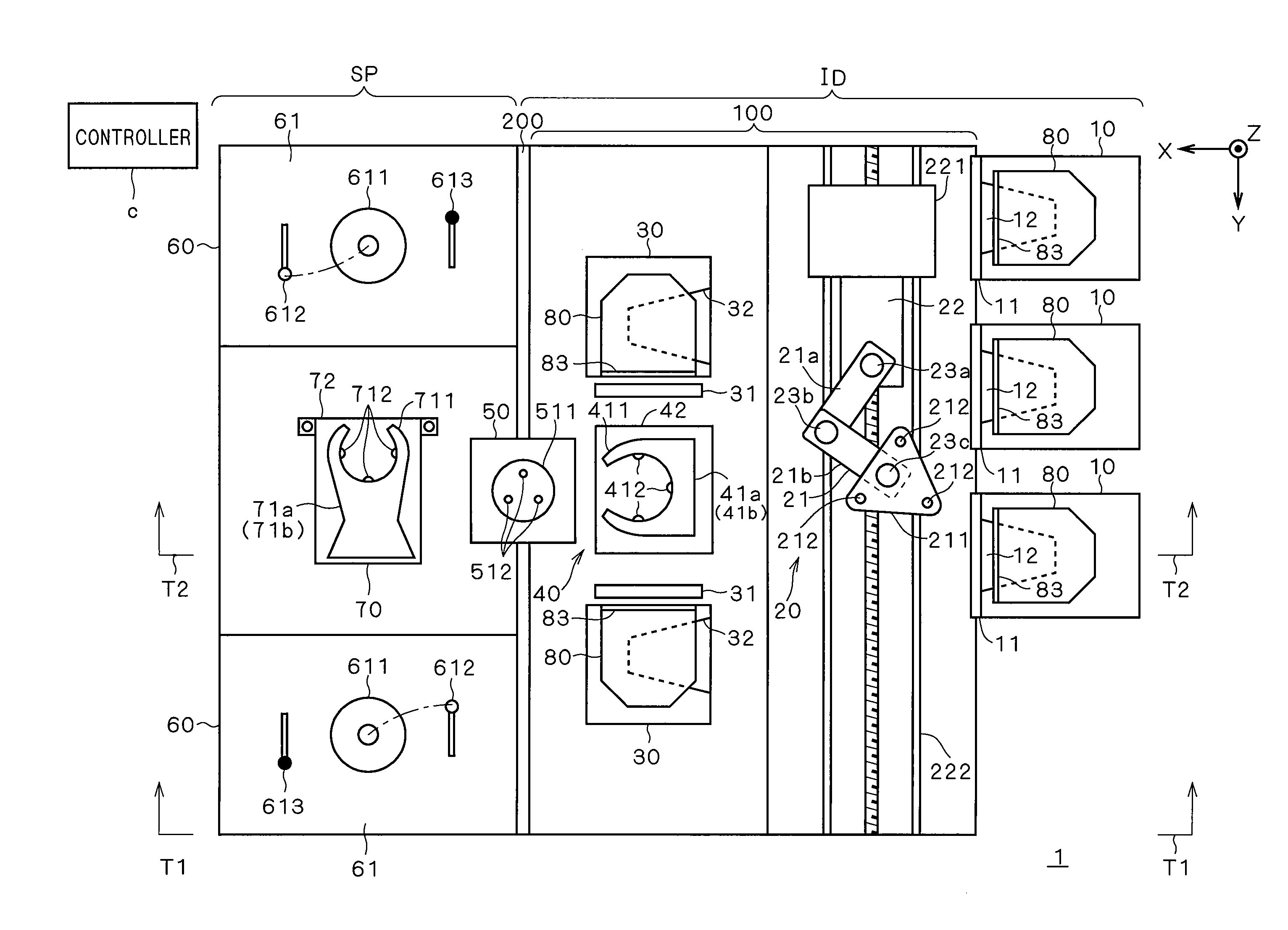
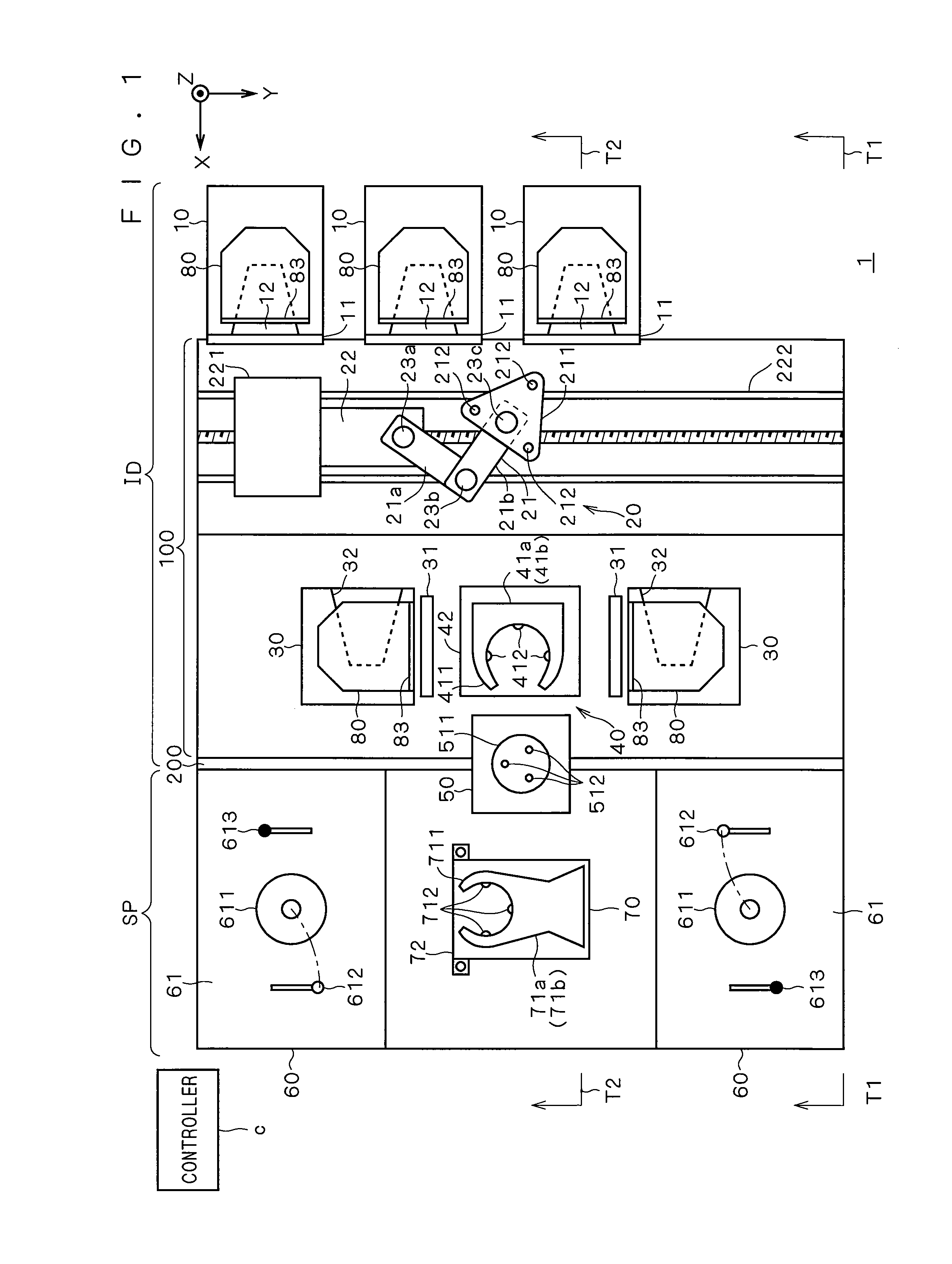
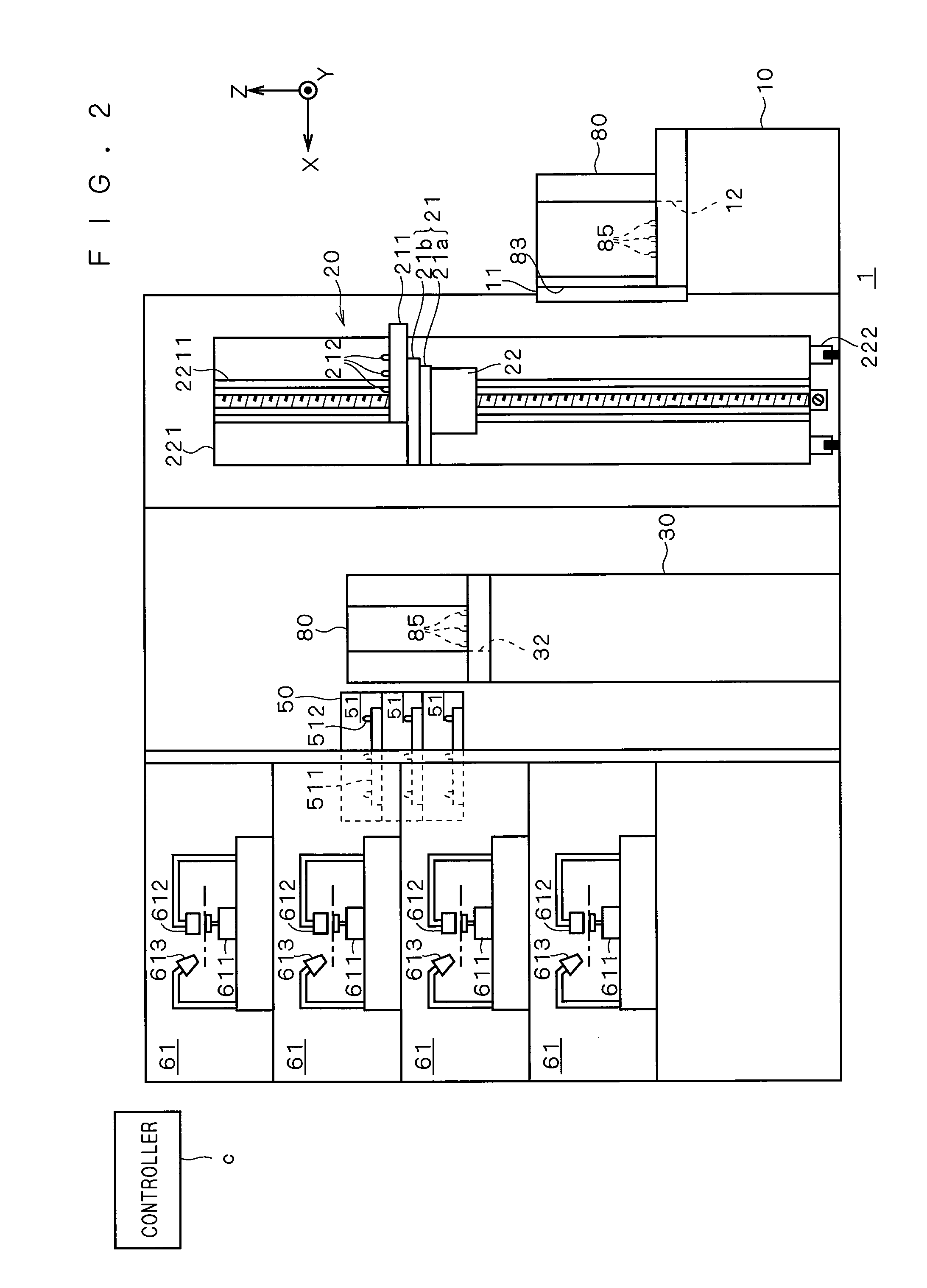
[0030]A configuration of a substrate processing apparatus according to a preferred embodiment of the invention is described with reference to FIGS. 1 to 3. FIG. 1 is a plan view of a substrate processing apparatus 1; FIG. 2 is a side sectional view of the substrate processing apparatus 1 as viewed in the direction of the arrow T1 in FIG. 1; and FIG. 3 is a side sectional view of the substrate processing apparatus 1 as viewed in the direction of the arrow T2 in FIG. 1. In order to clarify directional relationship of FIGS. 1 to 3 as necessary, FIGS. 1 to 3 additionally show an XYZ rectangular coordinate system where the Z-axis direction shall be a vertical direction and the XY plane shall be a horizontal plane.

[0031]The substrate processing apparatus 1 is a single-wafer-processing-type apparatus that scrubs and cleans a set of substrates (lots) stored in a front-opening unified pod...


PUM


Abstract

An FOUP transport robot transports an FOUP, which stores a plurality of substrates, between a loading port and an FOUP placement stage. An indexer robot transfers substrates (unprocessed substrates) stored in the FOUP placed on the FOUP placement stage, to a cleaning part through a substrate transfer part; or receives and stores substrates (processed substrates) subjected to scrub cleaning in the cleaning part, into the FOUP through the substrate transfer part. A plurality of FOUP placement stages are provided around the indexer robot, so that the indexer robot does not have to move in a horizontal direction at the time of transport.

Description

BACKGROUND OF THE INVENTION[0001]1. Field of the Invention[0002]The present invention relates to a substrate processing apparatus that processes a substrate such as a semiconductor substrate, a glass substrate for liquid crystal displays or for photomasks, or an optical disk substrate.[0003]2. Description of the Background Art[0004]Products such as semiconductors and liquid crystal displays are fabricated by processing a substrate as described above in a series of processing steps including cleaning, resist coating, exposure, development, etching, formation of an interlayer insulation film, heat treatment, dicing, and the like. A substrate processing apparatus performing such processing steps is configured by incorporating processing units that perform processing steps and a transport robot that transports substrates to each of the processing units.[0005]For instance, what is called a coater-and-developer is widely used, which is an apparatus that incorporates therein a coating unit...

Claims


Application Information

Patent Timeline
Patent Type & Authority Applications(United States)
IPC IPC(8): H01L21/677
CPCH01L21/67766H01L21/67778H01L21/67772Y10S414/137
Inventor MITSUYOSHI, ICHIRO
Owner DAINIPPON SCREEN MTG CO LTD
Why Eureka
Try Eureka