Method and apparatus for sharpening a tool blade

a tool blade and blade technology, applied in the field of woodworking tools, can solve the problems of difficulty in achieving the desired sharpening, prior art sharpening apparatus have proved difficult to operate to achieve the desired sharpening, and the user's manual sharpening of the tool working blade requires skill on the part of the user, so as to achieve the effect of convenient us

Active Publication Date: 2009-04-02
WOODPECKERS LLC
View PDF8 Cites 24 Cited by
  • Summary
  • Abstract
  • Description
  • Claims
  • Application Information

AI Technical Summary

Benefits of technology

[0010]The present invention provides an apparatus for sharpening a tool blade which is easily used by an amateur woodworker or skilled craftsman to sharpen and form both

Problems solved by technology

Although these devices, as well as other known sharpening apparatus and methods, have proved satisfactory, it has been found that the manual sharpening of the tool working blade requires skill on part of the user, which is not possessed by many amateur woodworkers, and prior art sharpening apparatus have proved diffi

Method used


Image

  • Method and apparatus for sharpening a tool blade
  • Method and apparatus for sharpening a tool blade
  • Method and apparatus for sharpening a tool blade

Examples


Embodiment Construction

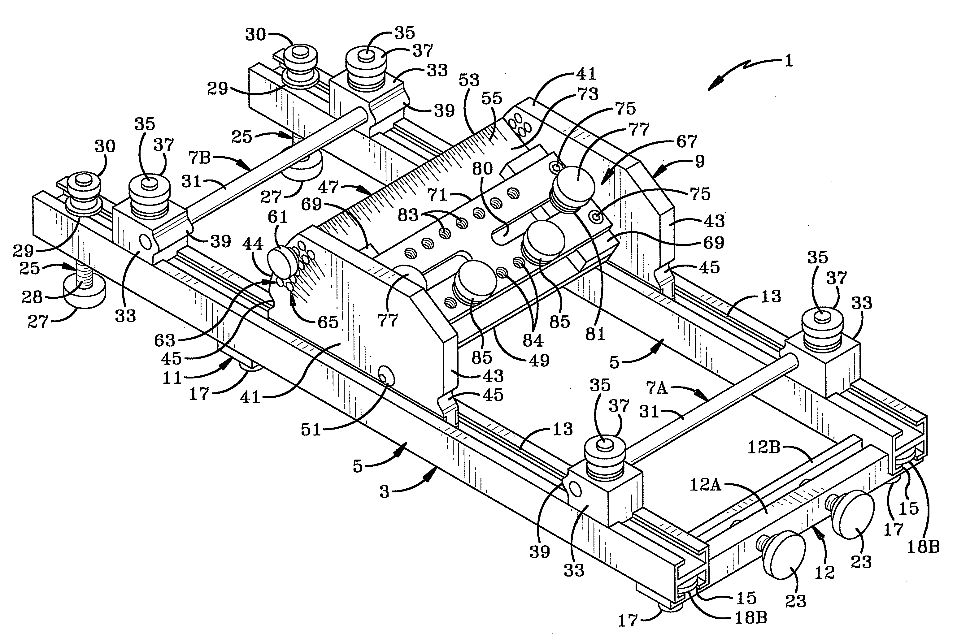
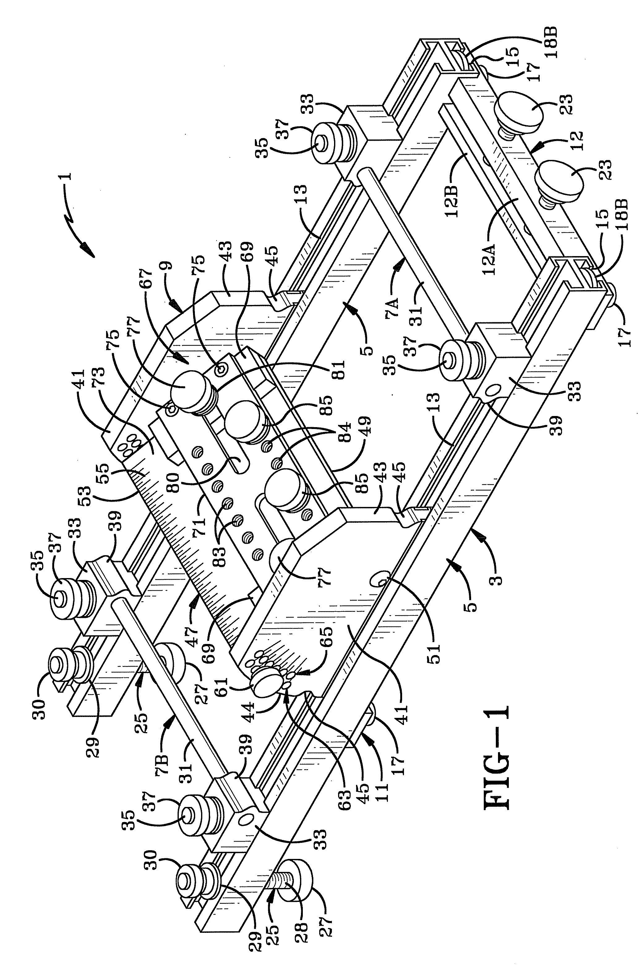
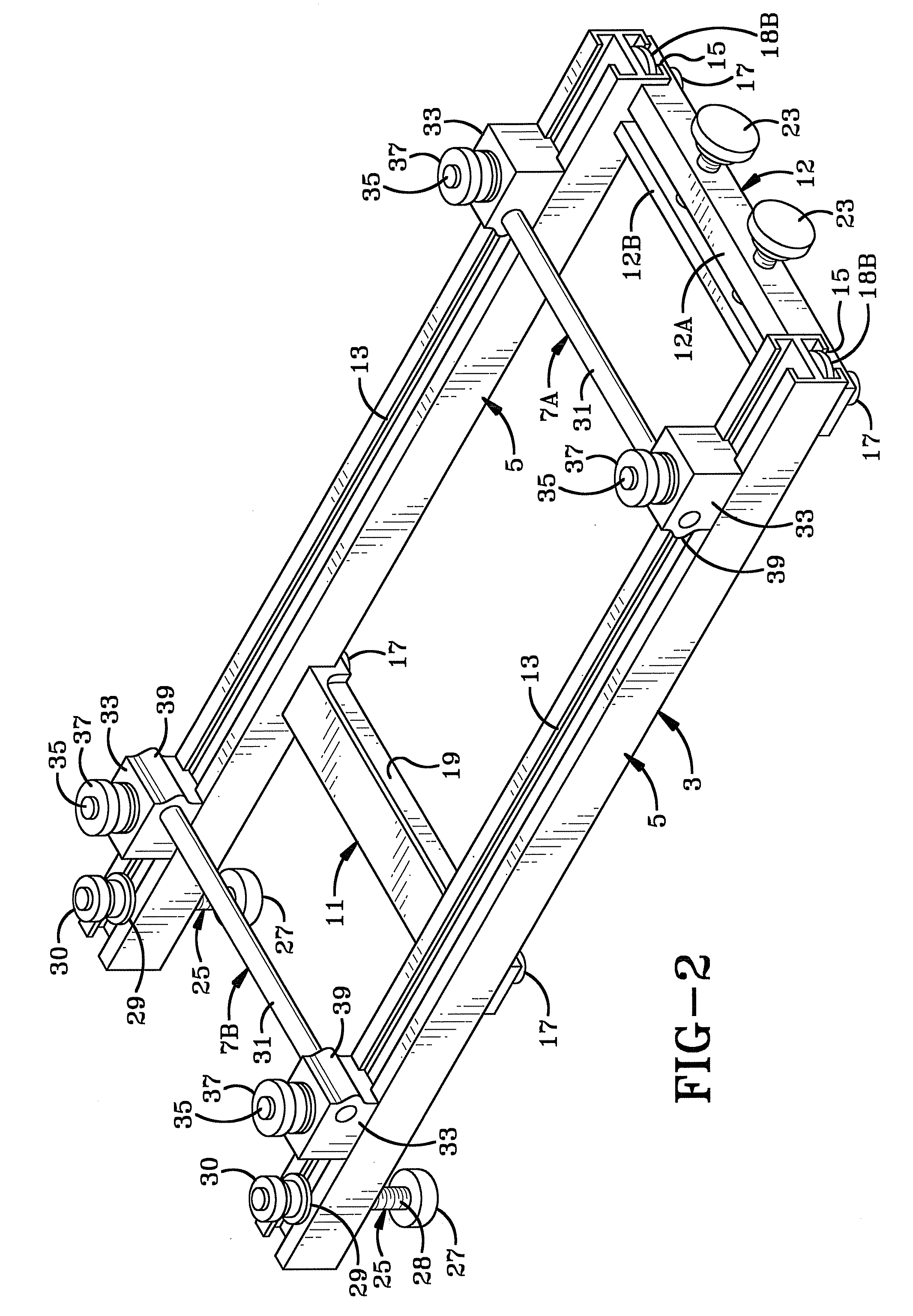
[0044]The apparatus of the present invention for sharpening a tool blade is indicated generally at 1, and is shown in an assembled operative position in FIG. 1. Sharpening apparatus 1 includes as its main components a support structure 3 which includes a pair of slide rails 5, a pair of stop brackets 7A and 7B and a carriage 9. Support structure 3 (FIG. 2) in addition to spaced slide rails 5, includes a pair of sharpening stone mounting brackets 11 and 12 mounted to slide rails 5. Each of the slide rails 5 is formed with a top slide channel 13 and a bottom slide channel 15 which extend throughout the longitudinal length of the slide rails.

[0045]Mounting bracket 11 (FIGS. 2 and 4) includes a pair of cap screws 17 which engage a pair of washers 18A and 18B for slidably mounting and locking bracket 11 in bottom slide channels 15. Thus, bracket 11 is slidably adjustably moved along slide rails 5 and then secured in an adjusted position by tightening screws 17, clamping washer 18B within...


PUM

PropertyMeasurementUnit
Angleaaaaaaaaaa
Widthaaaaaaaaaa

Abstract

A device for sharpening a tool blade has a pair of spaced guide rails and a bracket for mounting a sharpening stone on the guide rails. A carriage is slidably supported on the guide rails and has a pair of spaced slide plates adjustably supporting a blade angle plate thereon. A clamp mechanism secures the tool blade on the angle plate which is secured in an adjusted position for forming a primary angle on the blade cutting edge by reciprocal movement of the carriage along the guide rails. The angle plate and attached tool blade are readjusted on the carriage for subsequently forming a secondary angle on the cutting edge of the tool blade. Printed indicia adjacent a plurality of adjustment holes formed in the slide plates set the primary and secondary angles of the cutting edge. Mating surfaces on the carriage and guide rails set the amount of material to be removed from the blade during reciprocal movement along an abrasive sharpening material.

Description

CROSS REFERENCE TO RELATED APPLICATIONS[0001]This application claims priority from U.S. Provisional Application Ser. No. 60 / 975,612 filed Sep. 27, 2007; the disclosure of which is incorporated herein by reference.BACKGROUND OF THE INVENTION[0002]1. Technical Field[0003]The invention relates to woodworking tools, and in particular, to an apparatus for sharpening woodworkers' chisels, plane blades, various turning tools, etc. More particularly, the invention relates to an apparatus for use with sharpening stones and honing films for sharpening the beveled edges of a woodworking tool.[0004]2. Background Information[0005]Various devices have been used for sharpening the edges of woodworking tools, such as chisels, plane blades and certain types of turning tools. Many of these tools have a blade with a beveled edge which requires occasional sharpening by removing a certain amount of material from the beveled edge to maintain a sharp edge and the cutting efficiency of the tool. One common...

Claims


Application Information

Patent Timeline
IPC IPC(8): B24B19/00
CPCB24D15/06B24B3/34
Inventor HUMMEL, RICHARD M.
Owner WOODPECKERS LLC
Why Eureka
Try Eureka