
Ultrasound device

Active Publication Date: 2009-04-02
SIEMENS HEALTHCARE GMBH
View PDF11 Cites 48 Cited by
  • Summary
  • Abstract
  • Description
  • Claims
  • Application Information

AI Technical Summary

Benefits of technology

[0007]Contrary to previous standard practice, with the ultrasound device according to the invention, the operator no longer moves the ultrasound transducer. The movement of the ultrasound transducer is carried out by a robotic arm, which can be moved in space by at least three degrees of freedom, preferably six degrees of freedom. The more movable the robotic arm, the better the directional positioning of the ultrasound transducer that can be achieved by the corresponding arm control. In one embodiment of the robotic arm, by way of example as multi-articulated arm, which can be moved by six degrees of freedom, all longitudinal movements and also rotations around all spatial axes are possible, so that the ultrasound transducer can be moved to each position in the available movement capacity.
[0008]The use of a controlled robotic arm offers the possibility of automating the movement of the ultrasound transducer, so that the operator thus no longer has to move the head himself and search for the corresponding image acquisition positions, incurring the risk of not going to specific relevant positions, and hence not recording any images from there. Rather using the robot, it is possible for the movement operation of the ultrasound transducer to be controlled and automated, which can ensure that all relevant areas are actually captured and all the relevant image acquisition positions are covered.
[0010]Thereby, in a particularly practical embodiment of the invention, at least one part of the control curve, preferably all control curves, are assigned to specific examination areas or organs of the object to be examined. That means that area or organ-specific control curves, which define the optimal area or organ-specific movement paths, are stored for the image acquisition of specific examination areas or specific organs. This ensures that for each examination area or for each organ there is an optimal movement path and hence an optimal image acquisition at all-important positions and from all important transducer orientations.
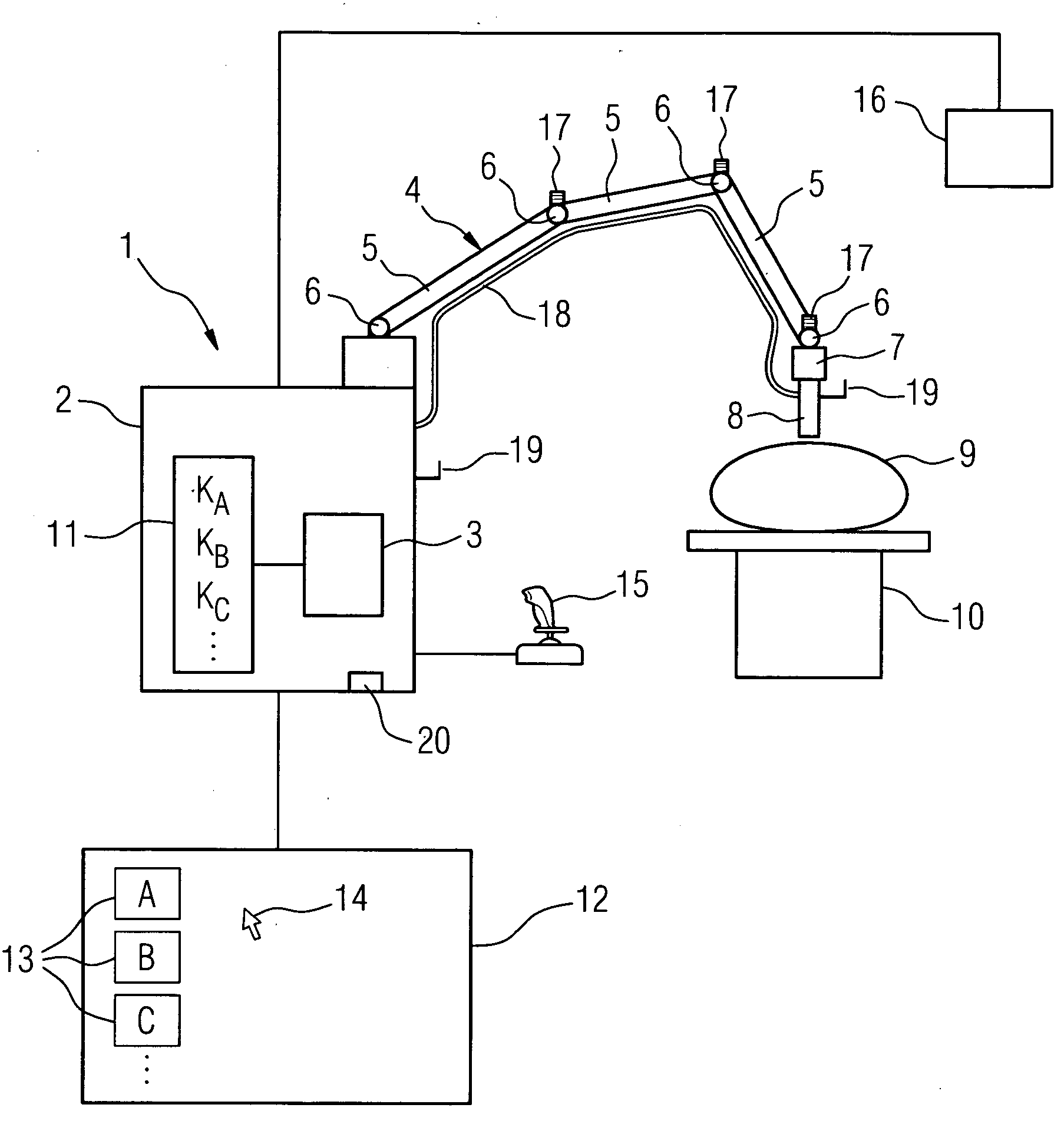
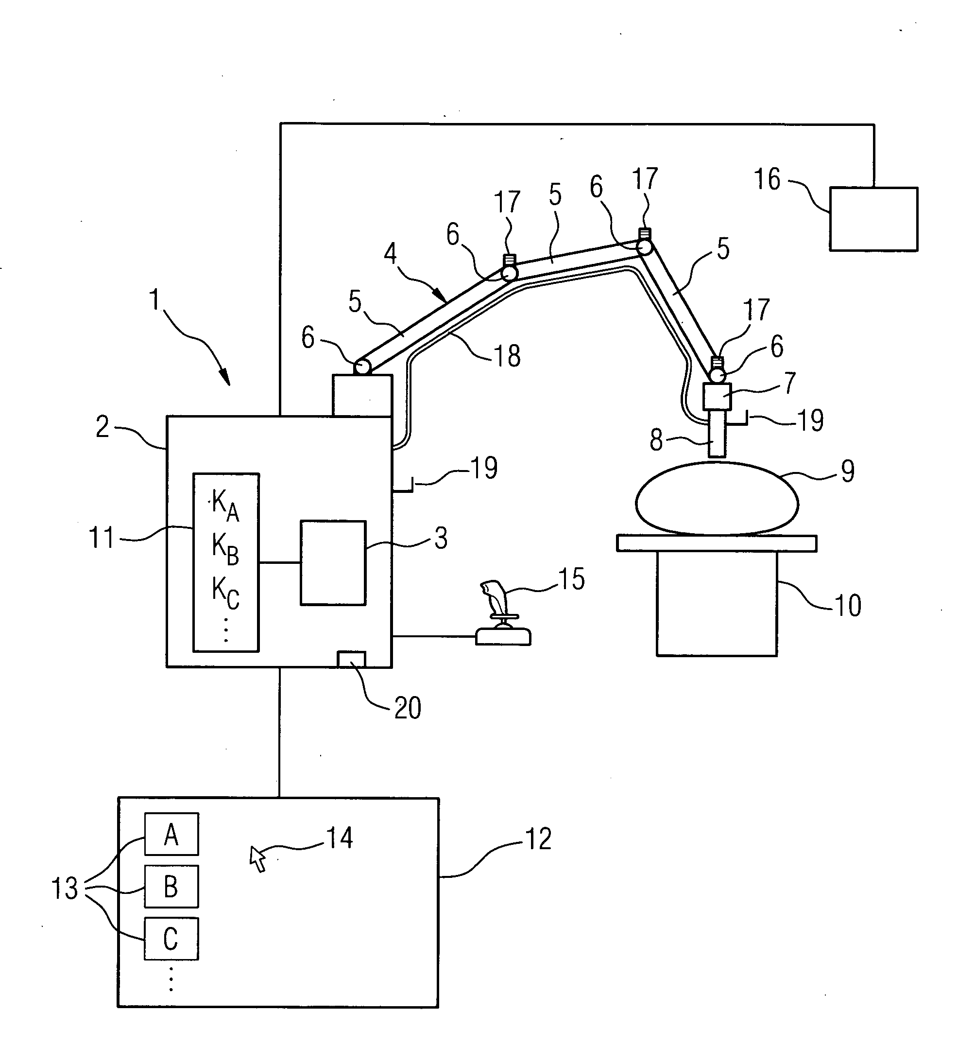
[0011]To simplify the selection of the required control curve for the operator, for practical purposes a selection device is provided, by means of which it is possible to select an examination area or an organ and hence the control curve assigned for use in the examination of the said organ or area. A display screen is conceivable for instance, on which specific examination areas (e.g. thyroid, pancreas, liver, etc.) are indicated by different icons or in written form. The operator can then use the screen cursor to select the desired examination area or the desired organ, whereupon at the control device, the control curve assigned to the area or organ is automatically selected and subsequently followed in the course of the image acquisition.
[0014]In addition, for practical purposes, means are provided on the robotic arm to prevent the ultrasound transducer placing inadmissible pressure on the object to be examined, this prevents the transducer being pressed too hard on the object to be examined, causing the patient either to feel pain for a brief moment or to be injured. Such means can comprise at least one force sensor and / or safety clutches in the region of arm joints. Through the means, regardless of what kind, an electronic control can carry out or if need be also stop the arm movement so that no inadmissibly high pressure occurs or so that, if the pressure were to rise inadmissibly, the movement would be stopped immediately and possibly reversed. Thus if, for example, several force sensors are used on the arm, then said sensors provide corresponding signals regarding any increase in force. The electronic control can then alter the speed of movement etc. Here it is also possible to make a corresponding optimization of the respective control curve in relation to the respective object to be examined. For example, if the ultrasound transducer is travelling over the abdominal wall, then the respective movement path in the case of a patient with a flat abdomen is somewhat different from that in the case of a patient with rounded abdomen. Using the corresponding means for preventing inadmissible high pressure, an increase in force can now be detected, which indicates that the ultrasound transducer, for example because of the corresponding abdomen rounding, must be raised a little so as to follow the shape of the abdomen without pressing too hard on the patient. That means that in this way it is possible for the ultrasound transducer movement to be adapted specifically to the object to be examined, by the control device continually detecting the force of the pressure or the application force and making corrective adjustments to the control curve, so as to control the physical circumstances according to the transducer movement.

Problems solved by technology

As not every operator has the appropriate experience in using the ultrasound transducer that is to be moved manually, there is the problem that despite in principle there being the possibility of recording images that show, for example, actually existing pathological findings, this is not recognized, as, as a consequence of the ultrasound transducer not being optimally guided, the relevant area was not recorded or not recorded with a sufficiently high diagnostic representation.

Method used


Image

  • Ultrasound device
  • Ultrasound device

Examples


Embodiment Construction

[0022]It shows an ultrasound device 1, comprising a device stand 2, in which a control device 3 is arranged, via which, in the example shown, the entire operation of the ultrasound device 1 is controlled. On the device stand 2 there is a robotic arm 4, which, in the example shown, is made up of three arm sections 5, which are joined by corresponding joints 6. On joint 6, shown on the right in the FIGURE, provision is also made for a holder 7 for an ultrasound transducer 8, which is moved over the surface of an object to be examined 9, which is arranged on a patient positioning table 10. The joints 6 are designed in such a way that they allow not only the individual arm sections 5 and possibly the holder 7 to be swiveled, but they also allow pivoting movements, so that there is a plurality of separate degrees of freedom for the arm movement.

[0023]The movement of the robotic arm 4 is controlled by the control device 3, which to this end activates corresponding actuators in the joint c...


PUM


Abstract

An ultrasound device is provided. The ultrasound device includes an ultrasound transducer to be moved along an object to be examined and a control device that communicates with the ultrasound device, controls the transmit and receive mode of the ultrasound transducer and processes the ultrasound signals received. The ultrasound transducer is arranged on a robotic arm that can be freely moved in space and controlled in terms of its movement.

Description

CROSS REFERENCE TO RELATED APPLICATIONS[0001]This application claims priority of German application No. 10 2007 046 700.3 filed Sep. 28, 2007, which is incorporated by reference herein in its entirety.FIELD OF INVENTION[0002]The invention relates to an ultrasound device comprising an ultrasound transducer that is to be moved along an object to be examined and a control device that communicates with said ultrasound device, controls the transmit and receive mode of the ultrasound transducer and processes the ultrasound signals received.BACKGROUND OF INVENTION[0003]Medical imaging is necessary to diagnose a large number of diseases. The oldest method, die X-ray technology, delivers high-resolution images within a short examination time, however, it has the disadvantage of exposing the patient to X-rays. Ultrasound imaging is a method of image acquisition that works without using radiation. With said ultrasound imaging, ultrasound signals are sent via an ultrasound transducer into the o...

Claims


Application Information

Patent Timeline
IPC IPC(8): A61B8/14
CPCA61B5/1127A61B8/4218A61B8/4281A61B19/2203A61B2019/2276A61B2019/465G05B2219/45117B25J11/00G05B19/423G05B2219/36513G05B2219/37269G05B2219/39439G05B2219/40198A61B2019/5276A61B34/30A61B2034/742A61B2090/065A61B2090/378
Inventor MASCHKE, MICHAEL
Owner SIEMENS HEALTHCARE GMBH
Learn More