
Optical aberration correction for machine vision inspection systems

a technology of optical aberration correction and machine vision, applied in the direction of speed/acceleration/shock measurement, measurement devices, instruments, etc., can solve problems such as significant z-height measurement variation (errors) and other problems, to achieve the effect of reducing memory and storage requirements, reducing processing time, and increasing the throughput of z-height determining operations

Active Publication Date: 2009-04-02
MITUTOYO CORP
View PDF21 Cites 35 Cited by
  • Summary
  • Abstract
  • Description
  • Claims
  • Application Information

AI Technical Summary

Benefits of technology

[0009]In many cases, the stronger or more apparent are the texture or line edges and / or directionality, the more significant are the astigmatism errors. Furthermore, it has been found that astigmatism errors may vary significantly over the camera field of view. That is, given a uniform directional texture throughout the field of view, a focus operation based on image data from one part of the field of view (from one ROI) may result in a different Z-height measurement than a focus operation based on image data from another part of the field of view (from another ROI). Such ROI-dependent astigmatism errors may be at least partially compensated or corrected by the systems and methods disclosed herein, to improve Z-height measurement accuracy and decrease measurement variability throughout a field of view.
[0021]In accordance with another aspect of the invention, a calibration target may consist of multiple differently-sized sets of respective target elements. Within each set, each of the respective target elements may be designed to be slightly larger than the field of view at the lowest magnification for which that particular set of target elements is designed. In addition, within each set, the density or spacing of any anisotropic features within the target element patterns (and isotropic features, if included) may be selected to provide good calibration with the magnification(s) that it is designed for, for example, the features should be “thick” enough in comparison to the camera pixel spacing so as to prevent aliasing, and there should be enough features in the field of view (e.g., lines and spaces, texture “scratches”, or the like) so as to provide a “strong” pattern in the field of view, particularly for the anisotropic target elements.
[0030]To avoid mechanical motion bottlenecks in various embodiments, it may be advantageous for a single global image stack (also referred to simply as a single, full, or global image stack, or the like) to be acquired and used as the basis for an entire multi-region and / or multi-subregion (e.g., multi-point tool subregions) height determination process, as described in greater detail below. In addition, it may be advantageous in various embodiments to base the orientation angle analysis operations outlined herein (in relation to respective Z height corrections) on respective image portions available within the global image stack, rather than on portions of additional “best possible” images acquired separately at the best possible focus position (e.g., separate images acquired at the determined Z-height or focus curve peak position).
[0036]It will be appreciated that each of the conditional operation methods outlined above, in comparison to prior art methods, may result in significantly reduced memory and storage requirements as images are acquired and processed during autofocus Z height determining operations. That is, image data (e.g., region or subregion data in various images in an image stack) may be suppressed or deleted at the earliest advantageous time (e.g., sequentially, during analysis), rather than acquired and retained until an entire image stack is completely analyzed. In one particular example embodiment, for non-overlapping regions or subregions of interest, the total amount of simultaneously stored information may be small enough to not exceed the size of a single image. In addition, the conditional operation methods outlined above may also significantly reduce processing time and increase throughput for Z height determining operations, particularly when providing anisotropic error correction for Z heights in multi-point auto focus tools with a large number of measurement subregions. Furthermore, the methods in certain embodiments integrate well with current autofocus tools in certain existing products.

Problems solved by technology

Such errors may be caused by lens aberrations such as astigmatism, as well as other features or imperfections of the machine vision optical system.
More specifically, the inventor has found that significant Z-height measurement variations (errors) may occur when measuring a surface or feature that exhibits “directional” features in the field of view.

Method used


Image

  • Optical aberration correction for machine vision inspection systems
  • Optical aberration correction for machine vision inspection systems
  • Optical aberration correction for machine vision inspection systems

Examples


Embodiment Construction

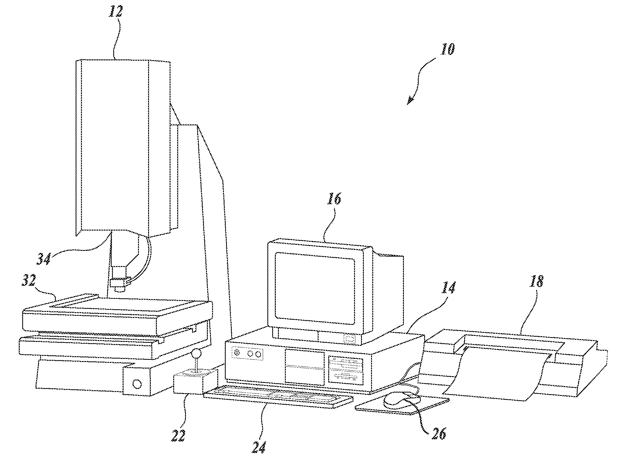
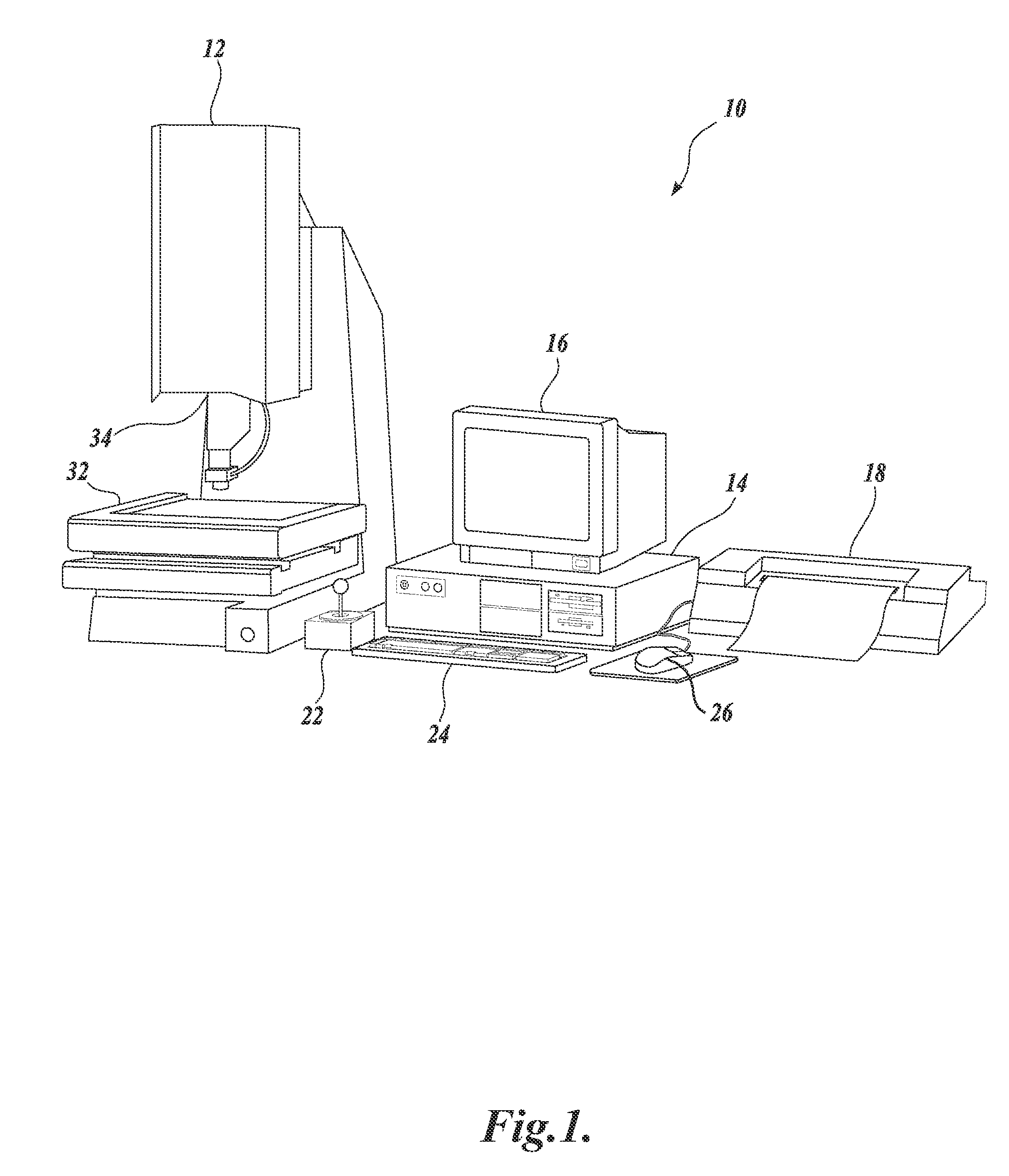
[0057]FIG. 1 is a block diagram of one exemplary machine vision inspection system 10 in accordance with the present invention. The machine vision inspection system 10 includes a vision measuring machine 12 that is operably connected to exchange data and control signals with a controlling computer system 14. The controlling computer system 14 is further operably connected to exchange data and control signals with a monitor 16, a printer 18, a joystick 22, a keyboard 24, and a mouse 26. The monitor or display 16, may display a user interface suitable for controlling and / or programming the operations of the machine vision inspection system 10.

[0058]The vision measuring machine 12 includes a moveable workpiece stage 32 and an optical imaging system 34 which may include a zoom lens or interchangeable lenses. The zoom lens or interchangeable lenses generally provide various magnifications for the images provided by the optical imaging system 34. The machine vision inspection system 10 is ...


PUM


Abstract

A system and method for correcting surface height measurements for optical aberration is provided. Heights determined by an autofocus tool, which may depend on surface feature angles in a focus region of interest (ROI) and on the ROI location in the field of view, are corrected based on a novel error calibration. Error calibration data includes height corrections for different feature angles in images, and for multiple locations in a field of view. Height corrections are determined by weighting and combining the angle dependent error calibration data, e.g., based on a gradient (edge) angle distribution determined in the ROIs. When Z-heights are determined for multiple ROIs in a field of view, storage of image data from particular images of a global image stack may be efficiently controlled based on determining early in processing whether a particular image is a sufficiently focused “near-peak” focused image or not.

Description

CROSS-REFERENCE TO RELATED APPLICATION[0001]This application is a continuation-in-part of U.S. patent application Ser. No. 11 / 263,002, filed Oct. 31, 2005, entire disclosure of which is hereby incorporated by reference.FIELD OF THE INVENTION[0002]The present invention relates to machine vision metrology systems, and more particularly, to a high-accuracy optical aberration correction system and method which corrects for errors (e.g., Z-height measurement errors) caused by lens aberrations such as astigmatism.BACKGROUND OF THE INVENTION[0003]Precision machine vision inspection systems (or “vision systems” in short) can be utilized to obtain precise dimensional measurements of inspected objects and to inspect various other object characteristics. Such systems may include a computer, a camera and optical system, and a precision stage that is movable in multiple directions so as to allow the camera to scan the features of a workpiece that is being inspected. One exemplary prior art syste...

Claims


Application Information

Patent Timeline
Patent Type & Authority Applications(United States)
IPC IPC(8): G01D18/00G06K9/00
CPCG01B21/045G01B11/0608
Inventor BRYLL, ROBERT K.DELANEY, MARK L.
Owner MITUTOYO CORP
Learn More