Water-cooling heat-dissipating module of electronic apparatus

a technology of electronic equipment and heat dissipation module, which is applied in the direction of lighting and heating equipment, domestic cooling equipment, semiconductor/solid-state device details, etc., can solve the problems of increasing the temperature of the soft conduit, generating excessive amounts of heat, and increasing the structure complexity. , to achieve the effect of reducing the temperature of the fluid and lowering the temperature of the heat-conducting uni

Inactive Publication Date: 2009-04-09
ASIA VITAL COMPONENTS SHENZHEN CO LTD
View PDF19 Cites 13 Cited by
  • Summary
  • Abstract
  • Description
  • Claims
  • Application Information

AI Technical Summary

Benefits of technology

[0008]The object of the present invention is to provide a water-cooling heat-dissipating module, in which water pipes are used to connect a driving unit, a heat-conducting unit and a dissipating unit. A fluid circulates in the above three components. Via the driving unit, the fluid is guided from the dissipating unit to flow into the heat-conducting unit. Further, the heat-conducting unit is provided on a heat-generating source. With the fluid being injected into the heat-conducting unit, the temperature of the heat-conducting unit can be lowered. At the same time, the remaining heat source can be carried away. The heat source is carried by the fluid and thus is guided back to the dissipating unit. The dissipating unit reduces the temperature of the fluid. The fluid whose temperature is reduced continues to circulate via the driving unit. An accommodating layer is provided in the top of the driving unit of the heat-dissipating module. The accommodating layer is provided with a water-guiding fan constituted of a plurality of fan blades. A water-guiding notch is provided at an adjacent position between each fan blade. Via this arrangement, when the water-guiding fan starts to rotate, the fluid flowing into the driving unit is delivered by a conduit connected with the water pipe, and then is injected into the heat-conducting unit. The fluid passes through a closed water-receiving space that is formed of a cover and chassis provided in the heat-conducting unit. After the fluid circulates in the closed water-receiving space continuously, the fluid drains out of the heat-conducting unit through a draining pipe of the cover, and is then delivered back to the dissipating unit via the water pipe for the subsequent cooling, thereby performing a cooling action continuously to the heat-dissipating module. Each unit is connected one another by means of the water pipes. In this way, the heat-generating source can be dissipated smoothly via the heat-dissipating module, thereby achieving the object of heat dissipation.

Problems solved by technology

Since the processing speed of an information apparatus needs to be higher and higher, a chip set is thus developed, which is more complicated in structure and generates relatively high pulses in operation.
As a result, excessive amount of heat is inevitably generated.
In view of this problem, since the conventional heat-dissipating module having heat-dissipating fins and heat-dissipating fans gradually becomes insufficient to complete the heat dissipation, a water-cooling heat-dissipating module is currently used.
However, since the above-mentioned heat-dissipating system is constituted of individual heat-dissipating assemblies, it is not an independent heat-dissipating structure that a plurality of soft conduits is used to interconnect individual components.
Since the heat-bearing capacity of the soft conduit is bad, after a long-term use in a hot environment, the connecting portion between the soft conduit and the water block becomes loose.
As a result, the cooling liquid flowing in the soft conduit may leak to the outside through the old and broken conduit, causing the electronic element to get damaged.
Further, because of the poor connection of conduits, the cooling liquid may evaporate gradually and external air may enter the interior of the conduits easily.
When the cooling liquid within the water-cooling system gradually evaporates and a lot of air exists in the conduits, the heat-dissipating efficiency will be deteriorated greatly.
On the other hand, insufficient heat-dissipating medium may cause a danger in use.
The above-mentioned problems have already been the primary issues for those skilled in this art.

Method used


Image

  • Water-cooling heat-dissipating module of electronic apparatus
  • Water-cooling heat-dissipating module of electronic apparatus
  • Water-cooling heat-dissipating module of electronic apparatus

Examples


Embodiment Construction

[0016]In order to achieve the above objects and effects, the special technical measures and structures utilized in the present invention will be explained in detail with reference to the accompanying drawings in terms of characteristics and functions of preferred embodiments of the present invention.

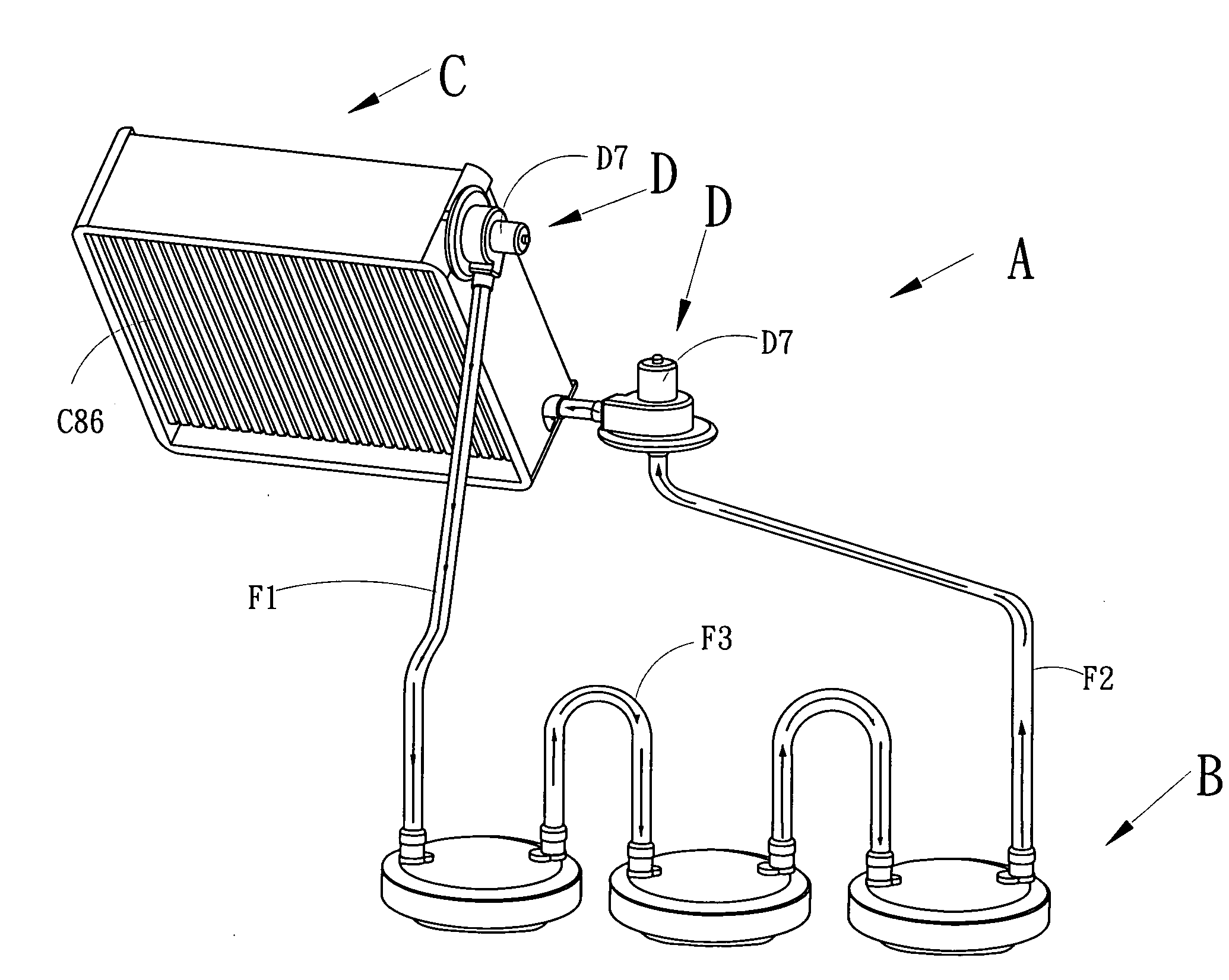
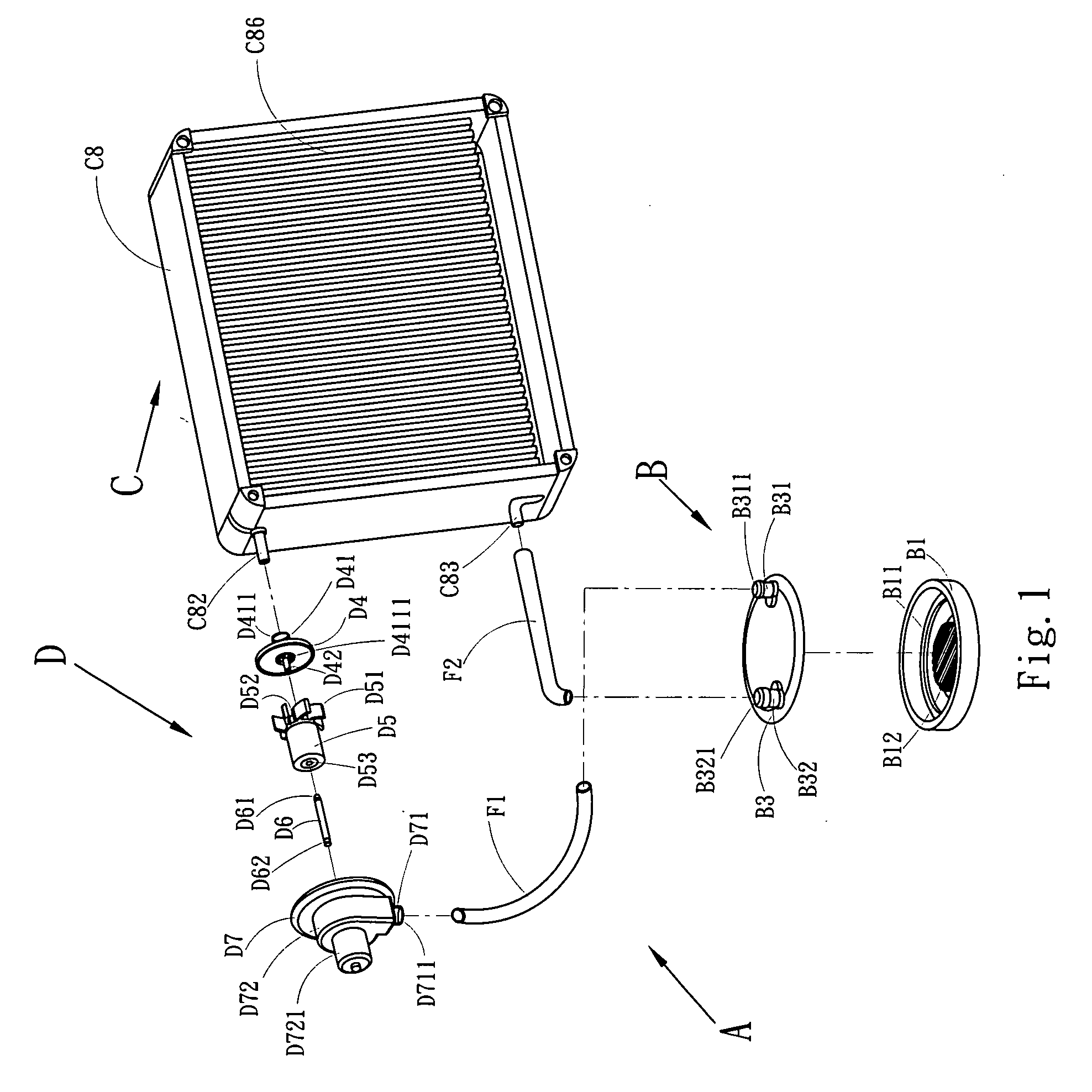
[0017]With reference to FIG. 1, it is an exploded perspective view of a preferred embodiment of the present invention. As shown in this figure, a heat-dissipating module A comprises three major units as follows.

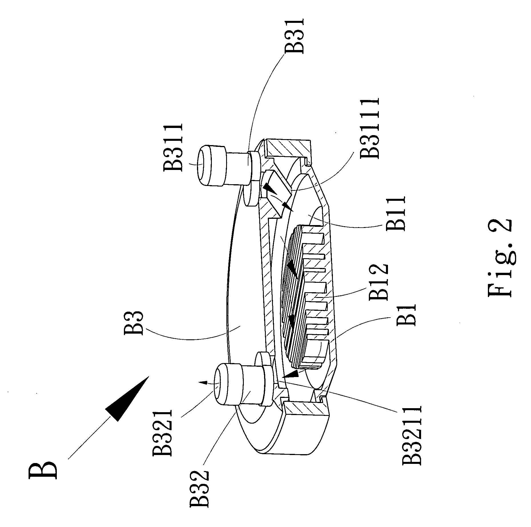
[0018]A heat-conducting unit A comprises a chassis B1 and a cover B3.

[0019]A dissipating unit C comprises a water tank C8, a draining hole C82, a water-injecting hole C83 and heat-dissipating fins C86.

[0020]The driving unit D comprises a water-guiding body D7, a spindle D6, a water-guiding fan D5 and a base D4.

[0021]Each of the units is interconnected to one another by means of a water pipe F1 and a water pipe F2.

[0022]The chassis B1 has a water-receiving space B11, and the chassi...


PUM


Abstract

A water-cooling heat-dissipating module of an electronic apparatus includes a heat-conducting unit, a driving unit and a dissipating unit. The heat-conducting unit has a function of conducting a heat source. The dissipating unit has a function of dissipating the heat of a fluid. The driving unit has a function of driving the fluid. Via the driving unit, the fluid can be rapidly introduced into or drained out of each unit for circulation, thereby achieving the heat-dissipating effect.

Description

BACKGROUND OF THE INVENTION[0001]1. Field of the Invention[0002]The present invention relates to a water-cooling heat-dissipating module of an electronic apparatus, and in particular to a water-cooling heat-dissipating module of an electronic apparatus, thereby accelerating the cooling of a fluid so as to facilitate the heat dissipation.[0003]2. Description of Prior Art[0004]With the progress of precise technologies, in order to execute some preset functions, the interior of a computer casing may be provided with some components, such as a central processing unit (CPU), displaying card, disk drive, sound effect card or the like. Some of these installed components have to consume a larger amount of heat in operation, such as the central processing unit (referred to as CPU) and displaying card (referred to as VGA1, VGA2). Such kind of heat-generating components need to forcibly dissipate the heat thereof generated in operation, thereby maintaining the normal operation of the component...

Claims


Application Information

Patent Timeline
Patent Type & Authority Applications(United States)
IPC IPC(8): F28F7/00F25D23/12H05K7/20F28D15/00F28D21/00
CPCH01L23/473H05K7/20254H01L2924/0002H01L2924/00
Inventor CHIANG, KUEI-FENG
Owner ASIA VITAL COMPONENTS SHENZHEN CO LTD
Why Eureka
Try Eureka