Cutting element having stress reduced interface

a cutting element and interface technology, applied in the field of cutting elements, can solve the problems of reducing the service life of the desired cutting element, so as to prolong the effective service life of the cutting element

Inactive Publication Date: 2009-04-09
SMITH INT INC
View PDF9 Cites 7 Cited by
  • Summary
  • Abstract
  • Description
  • Claims
  • Application Information

AI Technical Summary

Benefits of technology

[0012]Cutting elements comprising such feature can be used in such applications as with bits for drilling subterranean formations, where properties of reduced stress singularity is desired for the purpose of extending the effective service life of the cutting element.

Problems solved by technology

In is well known that the joint in such cutting elements can be subject to large amounts of stress during use of the cutting element caused by the existence of such elastic and thermal expansion property differences between the joined together materials.
This stress is known to cause cracking and / or delamination at the joint, between the ultra-hard body and the substrate, that can cause the cutting element to fail, thereby reducing the desired cutting element service life.
While such attempts have some effect in reducing some of the stresses existing along the interface between the ultra-hard body and substrate, under certain conditions, it is difficult to make a cutting element with a desired non-planar interface to suppress such stress.
For example, it is much more difficult to braze a TSP with non-planar interface to the substrate.

Method used


Image

  • Cutting element having stress reduced interface
  • Cutting element having stress reduced interface
  • Cutting element having stress reduced interface

Examples


embodiment 40

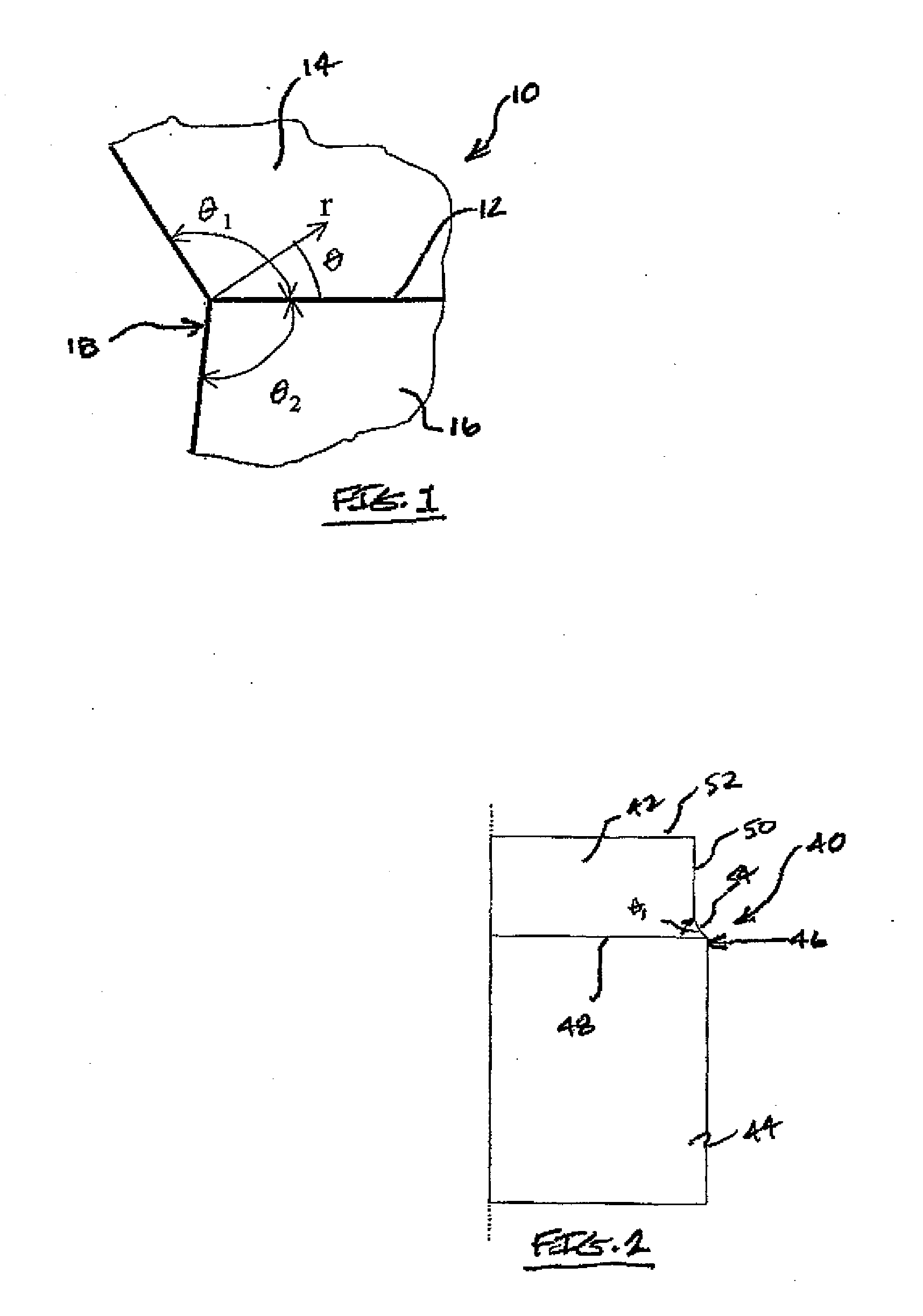
[0026]FIG. 2 illustrates a cutting element embodiment 40 comprising an ultra-hard body 42 that is attached to a substrate 44, wherein the materials used to form the ultra-hard body and substrate in this cutting element can be the same as those described above for forming conventional cutting elements. In an example embodiment, the ultra-hard body is formed from TSP and the substrate is formed from WC—Co. In this particular embodiment, the ultra-hard body 42 has been joined to the substrate 44 through the use of a braze material or the like. In this particular embodiment, the stress singularity was reduced by changing an angle of departure with the interface between the body and substrate to less than 90 degrees within the body by changing the geometry of a free surface or side surface 46 of the cutting element adjacent the interface 48.

[0027]In this particular embodiment, a side surface 46 of the ultra-hard body 42 has been configured to provide a desired angle of departure θ1 of le...

embodiment 80

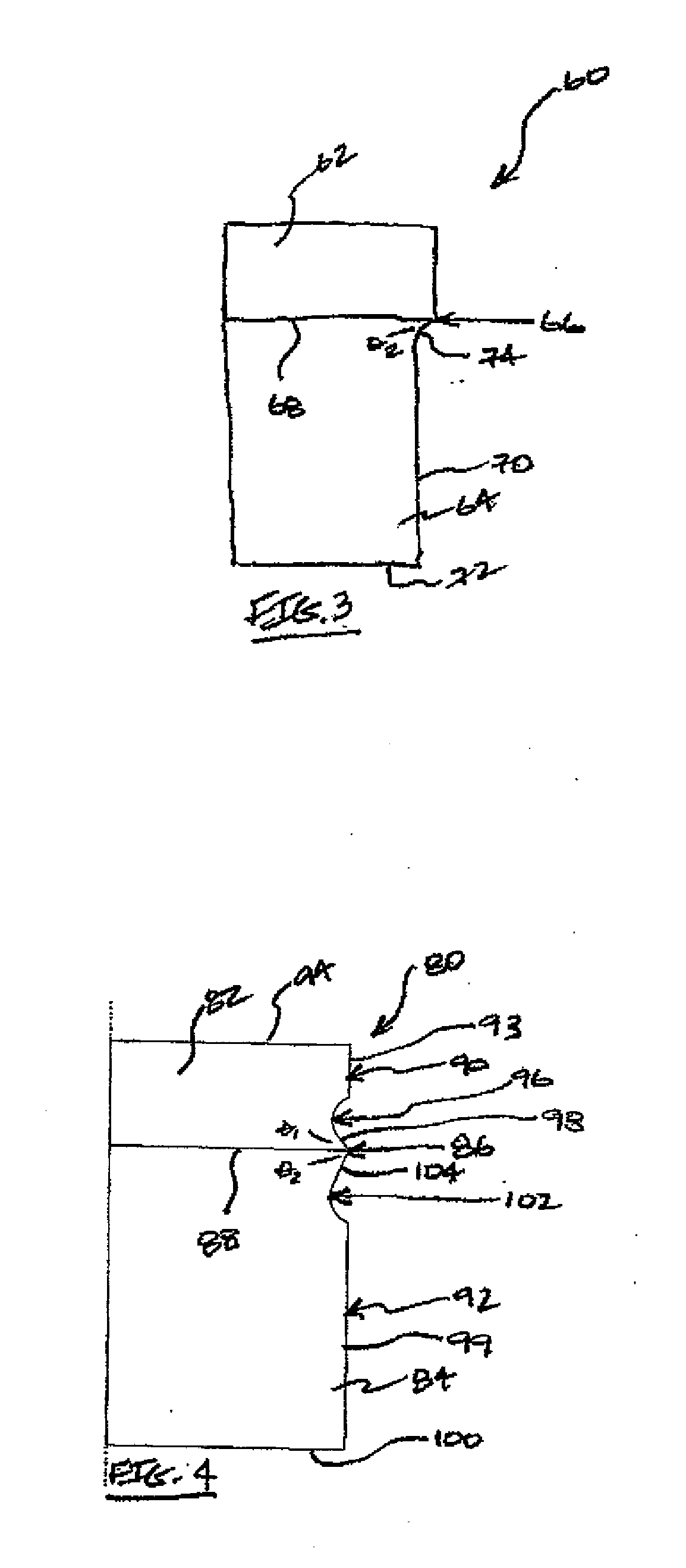
[0042]A feature of this cutting element embodiment 80 is that the presence of the grooves 96 and 102 in the respective side surfaces of the ultra-hard body 82 and substrate 84 operates to reduce the respective angles of departure θ1 and θ2 within each of the ultra-hard body and the substrate to less than 90 degrees, thereby reducing the stress singularity of the resulting cutting element. The angle of departure, and / or the particular geometry of the grooves and the respective flared region, that is provided according to this embodiment reflects a consideration of what is useful for reducing the stress singularity as noted above, as well any impact such change to the outer surface geometry of the cutting element could have on the cutting element performance and / or service life. The desired configuration of the hard-body and substrate side surfaces can be provided during sintering or by machining.

[0043]While the embodiment in FIG. 4 has been illustrated and described as having an ultr...


PUM

PropertyMeasurementUnit
angle of departureaaaaaaaaaa
angleaaaaaaaaaa
angleaaaaaaaaaa

Abstract

Cutting elements include an ultra-hard body, e.g., comprising diamond, that is attached to substrate, e.g., comprising a cermet. An interface exists between the body and the substrate, and an angle of departure as measured between the interface and a free edge of the cutting element within one or both of the body and substrate, is less than about 90 degrees to provide a desired stress reduction along the interface. The angle of departure can be from about 3 to 87 degrees. The desired reduced angle of departure is provided by a surface feature disposed along an outer side surface of the cutting element adjacent a free edge of the interface. The surface feature can in the form of a groove disposed circumferentially around the body and/or substrate outer side surface, that is configured to provide the desired reduced angle of departure within the body and/or substrate.

Description

FIELD OF THE INVENTION[0001]This invention relates to cutting elements comprising an ultra-hard region attached to a substrate and, more particularly, to cutting elements having an interface between the ultra-hard region and substrate that has been specifically engineered to reduce the stresses that occur near a free edge of the interface.BACKGROUND OF THE INVENTION[0002]The use of cutting elements comprising an ultra-hard body formed from an ultra-hard material such as diamond, polycrystalline diamond (PCD), thermally-stable polycrystalline diamond (TSP), cubic boron nitride (cBN), polycrystalline cubic boron nitride (PcBN) and the like, that is attached to a substrate formed from metallic or cermet materials is well known in the art. For example, cutting elements that are configured for use with bits for drilling subterranean formations are known to comprise an ultra-hard body that is formed from PCD or TSP and that is attached to a substrate formed from cemented tungsten carbide ...

Claims


Application Information

Patent Timeline
Patent Type & Authority Applications(United States)
IPC IPC(8): E21B10/52B23K31/12
CPCB22F2005/001B22F2998/00E21B10/5735C22C26/00C22C29/08B22F7/062B22F2003/245
Inventor SHEN, YUELIN
Owner SMITH INT INC
Why Eureka
Try Eureka