System and method for particulate sensor diagnostic

Active Publication Date: 2009-04-09
DELPHI TECH IP LTD
View PDF12 Cites 69 Cited by
  • Summary
  • Abstract
  • Description
  • Claims
  • Application Information

AI Technical Summary

Problems solved by technology

However, when the detector cannot sense the stimulus signal, then the detector is configured to generate a diagnostic signal indicative of a wiring fault.

Method used


Image

  • System and method for particulate sensor diagnostic
  • System and method for particulate sensor diagnostic
  • System and method for particulate sensor diagnostic

Examples


Embodiment Construction

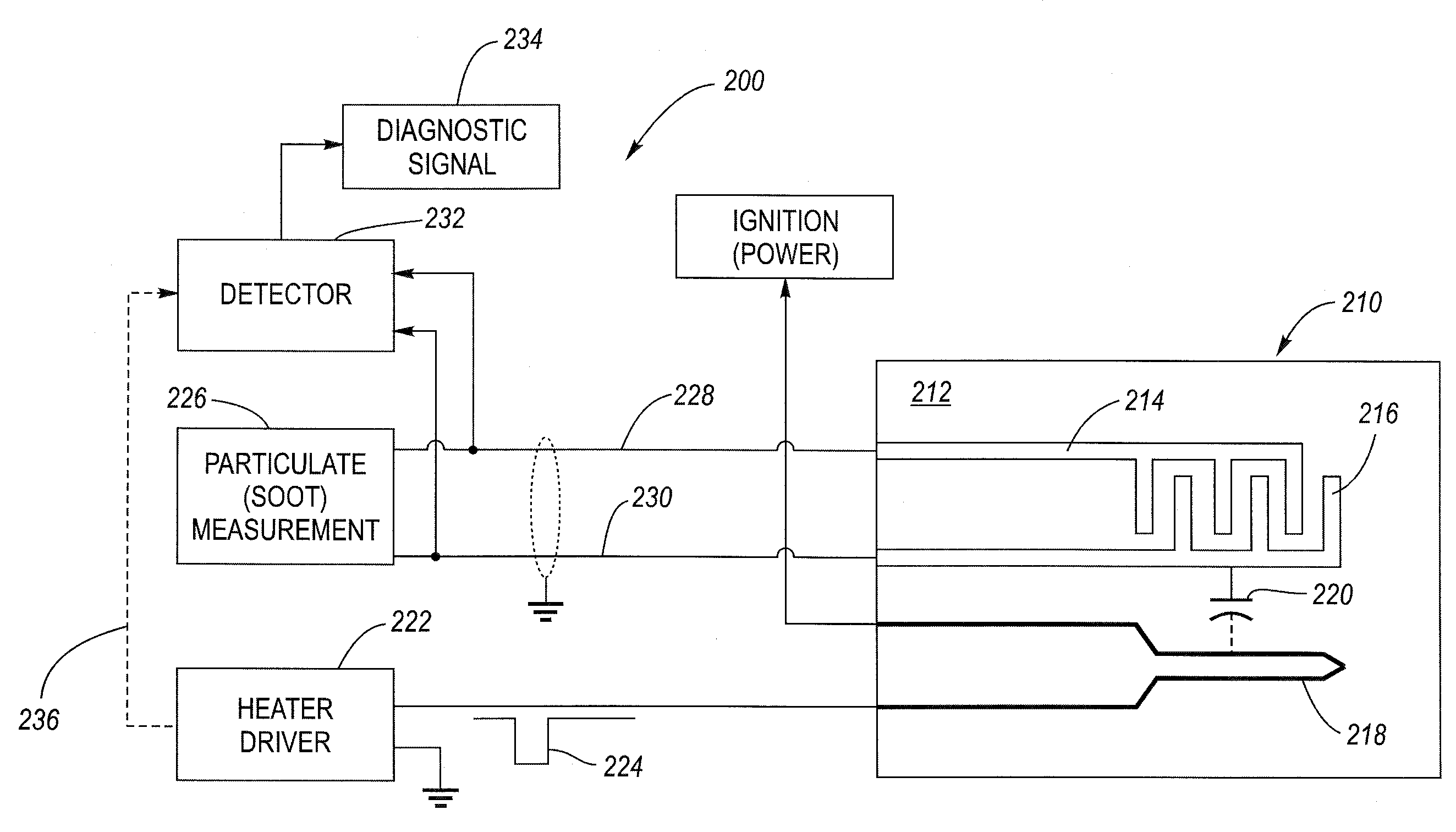
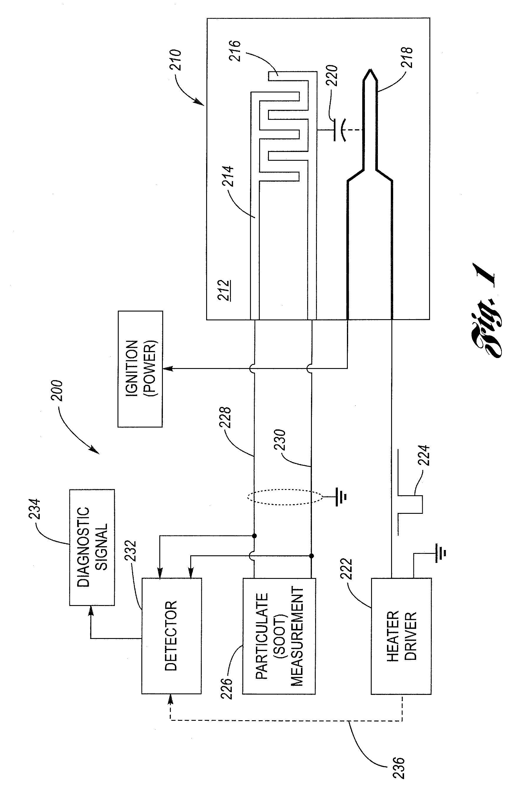
[0015]Referring now to the drawings wherein like reference numerals are used to identify identical components in the various views, FIG. 1 is a schematic and block diagram of a particulate sensor system 200 having a diagnostic feature for verifying the integrity of the wiring connections between the processing circuitry and the sensor. Sensor system 200 includes a particulate sensor 210 having (i) a substrate 212, (ii) first and second sensing electrodes 214, 216 and (iii) a heating electrode 218. Due to the construction of sensor 210, there exists a parasitic capacitance 220 between the heater electrode and the sensing electrodes. System 200 further includes processing circuitry comprising a heater driver 222 configured, among other things, to generate a stimulus signal 224, a particulate (soot) measurement circuit 226, and a detector 232 configured to generate a diagnostic signal 234.

[0016]The sensor 210 is the structure that is configured to sense a particulate concentration leve...


PUM

PropertyMeasurementUnit
widthaaaaaaaaaa
widthaaaaaaaaaa
widthaaaaaaaaaa

Abstract

A particulate (soot) sensor system has a diagnostic feature for verifying the integrity of the wiring leads. The sensor system includes a sensor and processing circuitry. The sensor has a substrate, first and second sensing electrodes on the substrate and a heater electrode. The heater electrode is electrically isolated from the first and second sensing electrodes, although there is a parasitic capacitance between them. The processing circuitry includes a heater driver, a measurement circuit connected to the sensing electrodes by wire leads, and a detector. The heater driver, in addition to energizing the heater, produces a stimulus signal that is applied to the heating electrode, which is then coupled via the parasitic capacitance to the sensing electrodes. The detector is coupled to the wiring leads and is configured to detect the stimulus signal when there is electrical conductivity over the leads to the sensing electrodes.

Description

TECHNICAL FIELD[0001]This invention relates generally to particulate sensor systems, and more particularly to a system and method for a particulate sensor diagnostic.BACKGROUND OF THE INVENTION[0002]It is known that incomplete combustion of certain heavy hydrocarbon compounds, such as heavy oils, diesel fuel and the like may lead to particulate formation (e.g., soot). In the operation of internal combustion engines, “smoking” of the engine leads to ambient air pollution although the carbon monoxide and hydrocarbon emission of the exhaust gases itself are relatively low. It is further known to provide a particulate sensor system for detecting the level of particulate concentration emitted from an exhaust gas, as seen by reference to U.S. Pat. No. 6,634,210 entitled PARTICULATE SENSOR SYSTEM issued to Bosch et al, assigned to the common assignee of the present invention and hereby incorporated by reference in its entirety.[0003]Bosch et al. disclose a particulate sensor system having ...

Claims


Application Information

Patent Timeline
Patent Type & Authority Applications(United States)
IPC IPC(8): G01N27/26G01N27/30G01R31/04
CPCG01N35/00613G01N15/0656
Inventor RIPLEY, EUGENE V.
Owner DELPHI TECH IP LTD
Why Eureka
Try Eureka