
Level shifter concept for fast level transient design

a level shifter and transient design technology, applied in the field of display panels, can solve the problems of large leakage current, affecting the normal operation of the circuit and the transition ability of the level shifter, and level shift units with poor transition ability will be easily influenced, and cannot transit successfully

Inactive Publication Date: 2009-04-09
HIMAX TECH LTD
View PDF8 Cites 2 Cited by
  • Summary
  • Abstract
  • Description
  • Claims
  • Application Information

AI Technical Summary

Benefits of technology

The present invention provides a driver that can sequentially transition multiple level shifters without generating high current levels simultaneously. The driver includes a shift register, latch units, and level shift units that work together to transfer voltage levels of signals sequentially. The driver also includes switches that control the latching of signals, ensuring that each level shifter can successfully transition. The driver enables the latch units sequentially, allowing each level shifter to successfully perform the transition. The driver ensures that each level shifter can sequentially transition a signal, avoiding simultaneous transitions that may cause high current levels. This driver design ensures that the driving circuit operates within a normal range of operating voltage, maintaining the ability to transition voltage levels.

Problems solved by technology

When a large number of level shifters perform voltage transition at the same time, a large leakage current will occur.
As a conductive path has a parasitic resistor, when the leakage current becomes too large, the voltage level at the ground terminal is increased, thus affecting the normal operation of the circuit and the transition ability of the level shifters.
At this time, the level shift units with poor transition ability will be easily influenced and cannot transit successfully.

Method used


Image

  • Level shifter concept for fast level transient design
  • Level shifter concept for fast level transient design
  • Level shifter concept for fast level transient design

Examples


Embodiment Construction

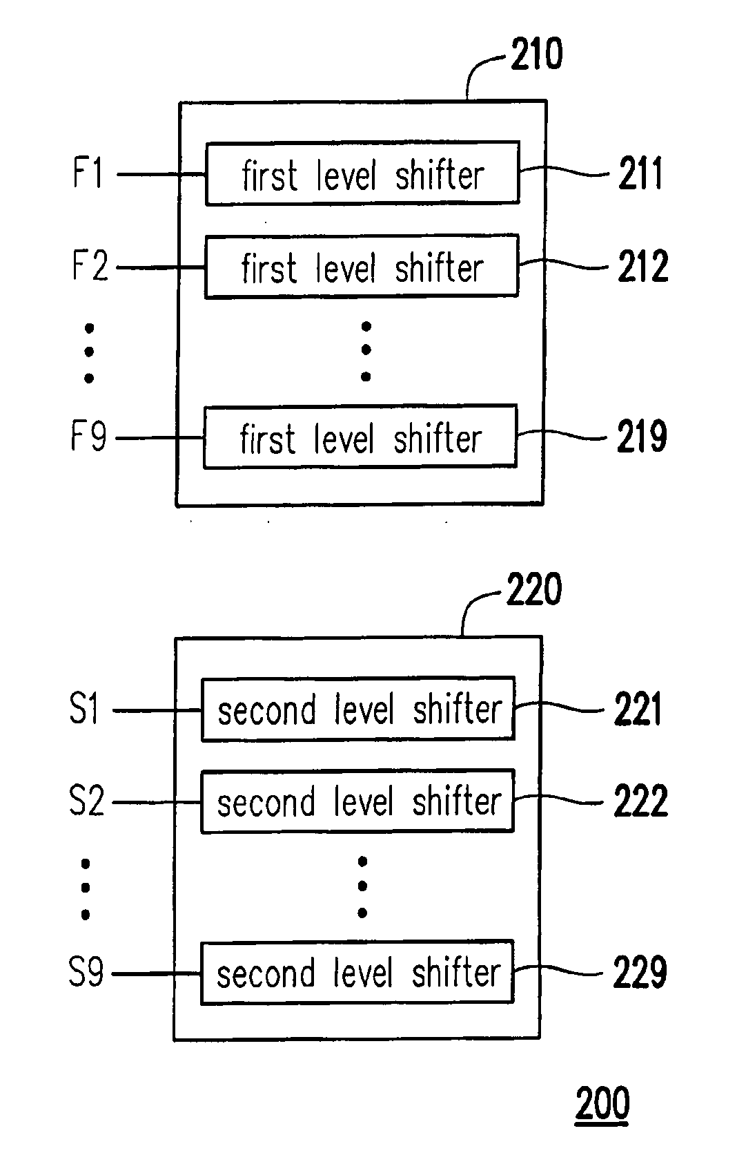
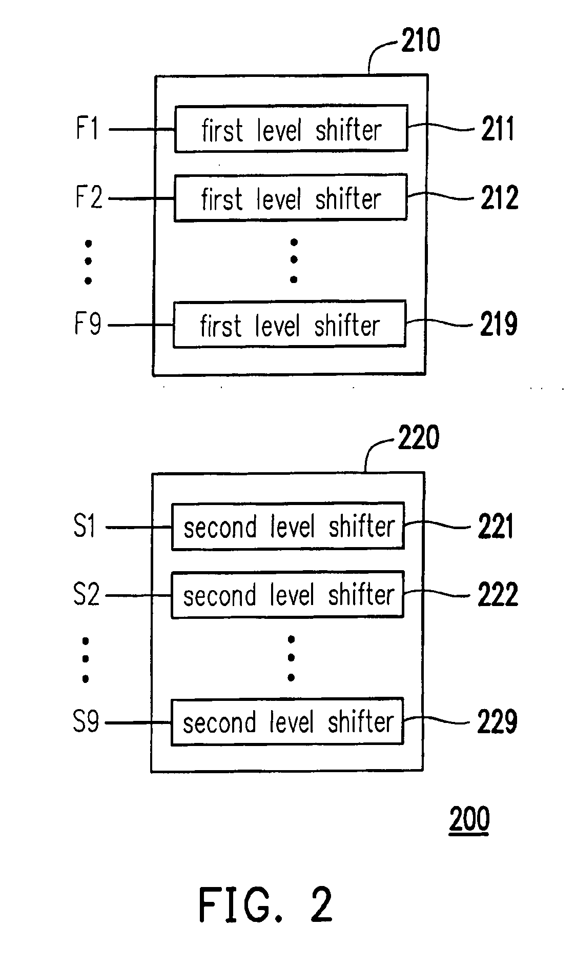
[0024]FIG. 2 is a circuit diagram of a driver according to an embodiment of the present invention. The driver 200 includes a plurality of level shifters, and the level shifters are divided into two groups, namely a first level shifter group 210 and a second level shifter group 220. The first level shifter group includes a plurality of first level shifters 211-219 for receiving first input signals F1-F9. Meanwhile, the second level shifter group 220 includes a plurality of second level shifters 221-229 for receiving second input signals S1-S9. When the transition of the first input signals F1-F9 and the second input signals S1-S9 respectively received by the first level shifters 211-219 and the second level shifters 221-229 occurs, the driver 200 sequentially enables the first level shifter group 210 and the second level shifter group 220, so as to sequentially transfer the voltage levels of the first input signals F1-F9 and the second input signals S1-S9. As the level shifters do no...


PUM


Abstract

A driver including a first level shifter group and a second level shifter group is provided. The first level shifter group includes at least one first level shifter to receive a first input signal. The second level shifter group includes at least one second level shifter to receive a second input signal. The driver sequentially enables the first level shifter group and the second level shifter group to sequentially transfer voltage levels of the first input signal and the second input signal.

Description

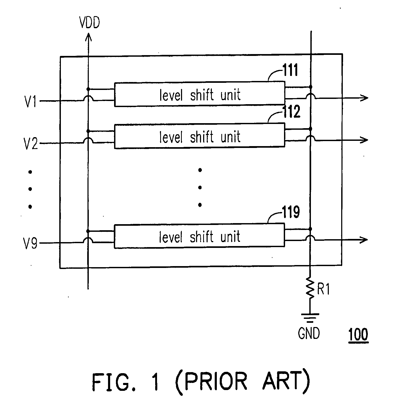
BACKGROUND OF THE INVENTION[0001]1. Field of the Invention[0002]The present invention relates to a display panel. More particularly, the present invention relates to a driver and a control method thereof.[0003]2. Description of Related Art[0004]In a source driver or a gate driver of a liquid crystal display (LCD), the voltage level must be transferred. When a large number of level shifters perform voltage transition at the same time, a large leakage current will occur. As a conductive path has a parasitic resistor, when the leakage current becomes too large, the voltage level at the ground terminal is increased, thus affecting the normal operation of the circuit and the transition ability of the level shifters.[0005]FIG. 1 is a driving circuit diagram in the conventional art. Referring to FIG. 1, the driving circuit 100 includes a plurality of level shifters 111-119, and the resistor R1 represents a parasitic resistor on the path of the ground terminal GND. When voltage transition o...

Claims


Application Information

Patent Timeline
Patent Type & Authority Applications(United States)
IPC IPC(8): H03L5/00
CPCG09G3/3688G09G3/3677
Inventor CHIOU, YU-WEN
Owner HIMAX TECH LTD
Learn More