Planar illuminating device

a lighting device and planar technology, applied in lighting and heating apparatus, waveguides, instruments, etc., can solve the problems of uneven light amount distribution and difficulty in achieving a thickness of 10 mm or less with a direct illumination type backlight unit, and achieve the effect of reducing unevenness, thin design, and reducing unevenness

Active Publication Date: 2009-04-09
FUJIFILM CORP
View PDF4 Cites 40 Cited by
  • Summary
  • Abstract
  • Description
  • Claims
  • Application Information

AI Technical Summary

Benefits of technology

[0030]A planar lighting device according to the first aspect of the present invention has the light guide plate disposed between the first light source and the second light source provided a given distance apart from each other. The light guide plate comprises the light exit plane having a rectangular external shape, the first light entrance plane facing the first light source, and the second light entrance plane facing the second light source. The light guide plate is shaped such that its thickness increases from the first light entrance plane and the second light entrance plane to the center and contains scattering particles for scattering light propagating through the inside. Configured as described above, the planar lighting device allows a thinner design to be achieved and is capable of emitting planar illumination light that is uniform with a reduced level of unevenness.
[0031]The planar lighting device according to the second aspect of the present invention comprises between the first light source and the second light source a light guide member comprising plastic optical fibers disposed in close contact with one another in layers and containing scattering particles that scatter light propagating therethrough. On one side of the plastic optical fibers is provided the first light source; on the other side is provided the second light source. Configured as described above, the planar lighting device allows a thin form to be achieved and is capable of emitting planar illumination light that is uniform with a reduced level of unevenness.

Problems solved by technology

While demands of still thinner backlight units are expected to grow in the future, achieving a thickness of 10 mm or less with a direct illumination type backlight unit is deemed difficult in view of uneven light amount distribution expected to accompany that type.

Method used


Image

  • Planar illuminating device
  • Planar illuminating device
  • Planar illuminating device

Examples


first embodiment

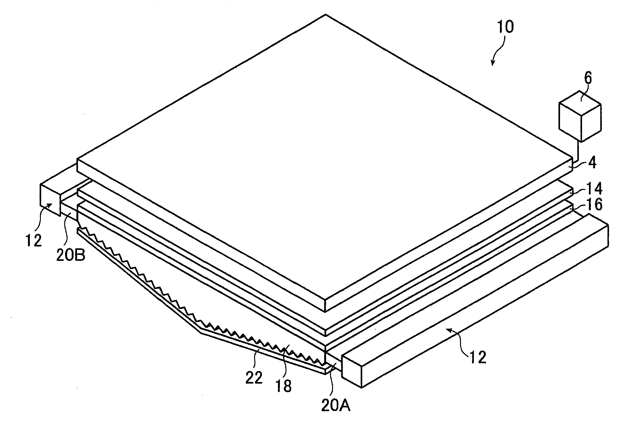
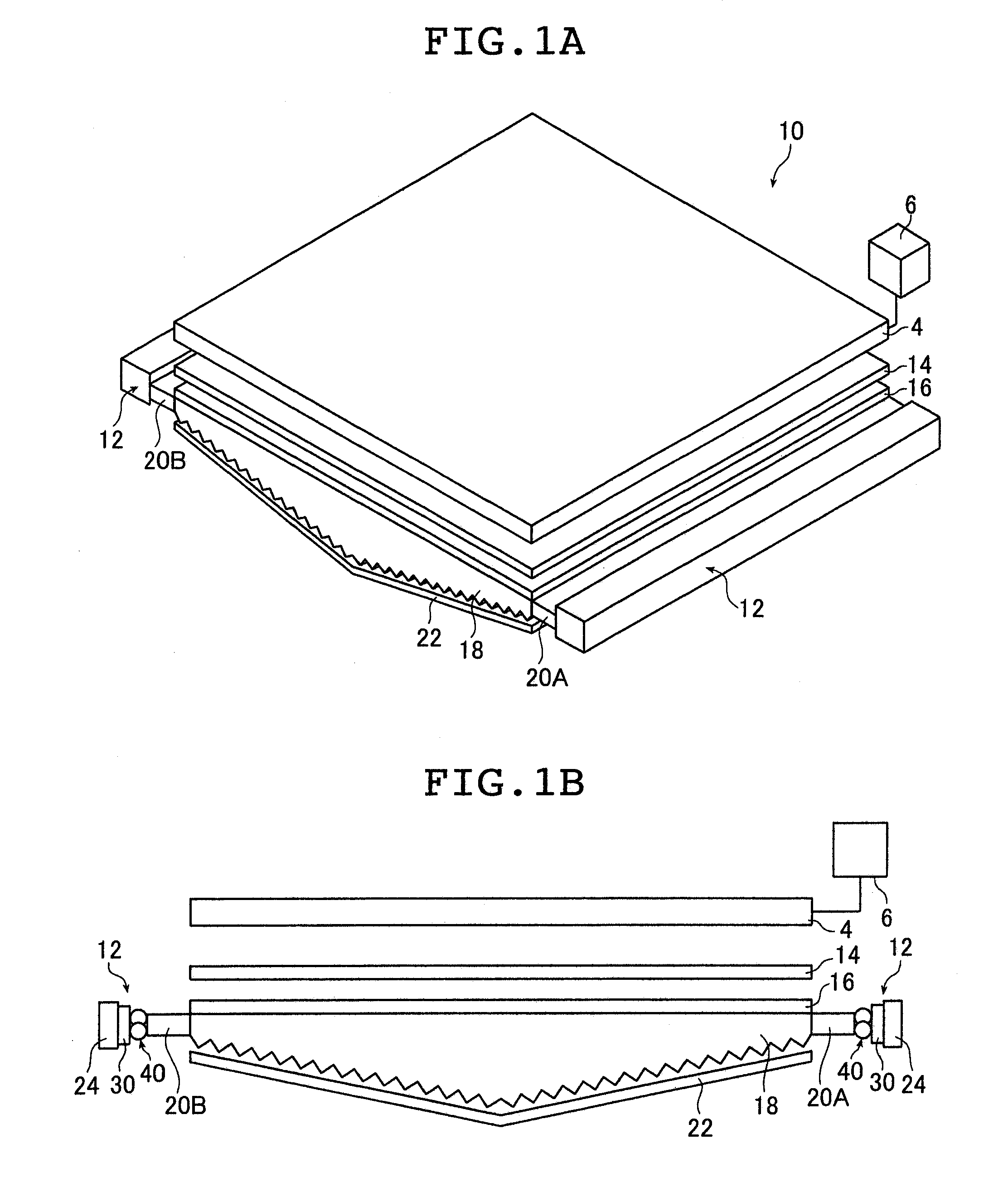
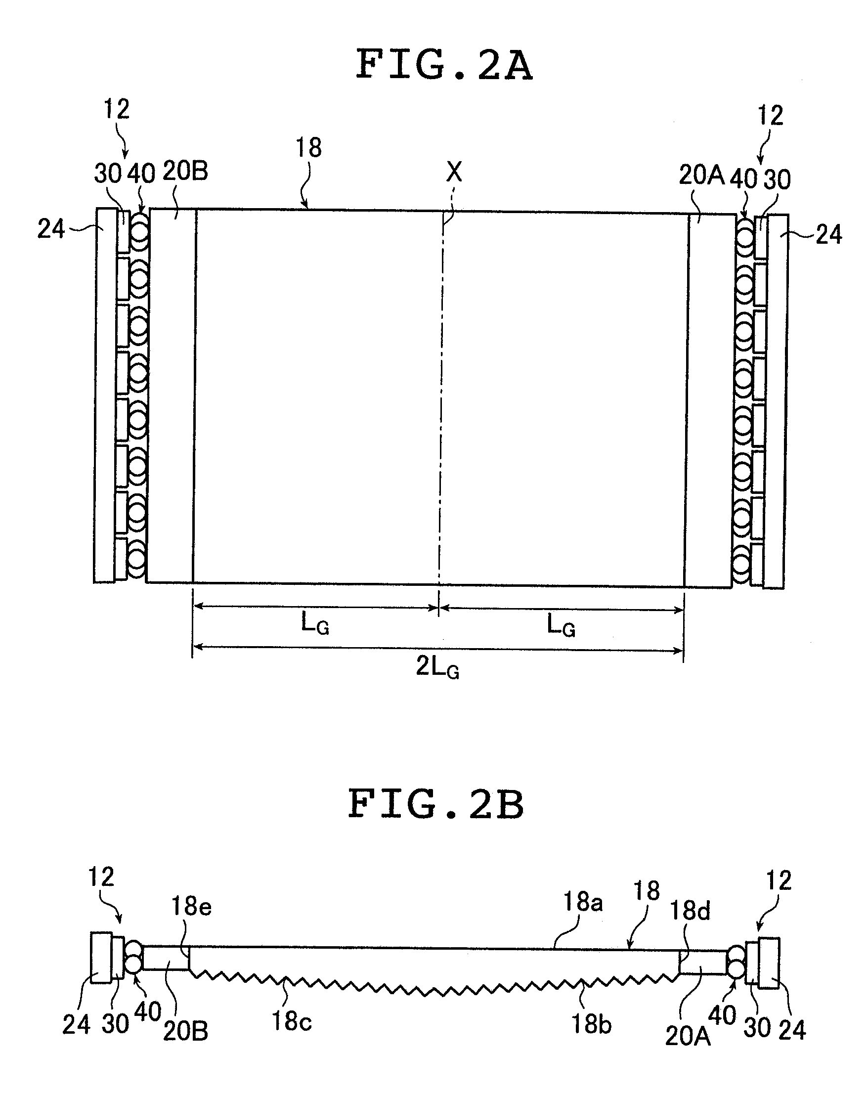
[0115]FIG. 1A is a schematic perspective view of a liquid crystal display device provided with the planar lighting device according to the present invention; FIG. 1B is a schematic sectional view of the liquid crystal display device. FIG. 2A is a schematic plan view of a light guide plate and light sources used in the inventive planar lighting device (hereinafter referred to as backlight unit); FIG. 2B is a schematic sectional view of the light guide plate.

[0116]A liquid crystal display device 10 comprises a backlight unit 2, a liquid crystal display panel 4 disposed on the side of the backlight unit closer to the light exit plane, and a drive unit 6 for driving the liquid crystal display panel 4.

[0117]In the liquid crystal display panel 4, electric field is partially applied to liquid crystal molecules previously arranged in a given direction to change the orientation of the molecules. The resultant changes in refractive index in the liquid crystal cells are used to display charact...

second embodiment

[0417]Next, the inventive planar lighting device will be described.

[0418]In the second embodiment, the planar lighting device is configured using a light guide member illustrated in FIGS. 33A and 33B. FIG. 33A is a schematic plan view illustrating part of the light guide member according to the second embodiment and a light source used to admit light into the light guide member; FIG. 33B is a schematic sectional view of the light guide member of FIG. 33A taken in line B-B.

[0419]The light guide member 90 is configured with a plurality of plastic optical fibers (POF) 92 and a transparent case 94 housing them as illustrated in FIG. 33B. The plastic optical fibers (simply referred to as optical fibers below) 92 and the case 94 are both formed of a flexible material. As illustrated in FIG. 33B, the plastic optical fibers (simply referred to as optical fibers below) 94 are each provided most closely inside the case 94 such that the spaces between the optical fibers are the smallest possib...


PUM


Abstract

Provided is a planar lighting device having a thin shape and capable of emitting uniform illumination light with less brightness unevenness. The planar lighting device includes a first and a second light sources arranged at a given distance apart from each other and a light guide plate arranged between the first and second light sources. The light guide plate includes a light exit plane, a first light entrance plane facing the first light source and containing one side of the light exit plane, and a second light entrance plane facing the second light source and containing the opposite side to the one side, and has a shape growing thicker from the first and second light entrance planes toward the center. The light guide plate contains scattering particles for scattering light entering through the first and second light entrance planes and propagating inside by a ratio satisfying 1.1≦Φ·Np·LG·KC≦8.2.

Description

TECHNICAL FIELD[0001]The present invention relates to a planar lighting device used in liquid crystal display devices and the like.BACKGROUND ART[0002]Liquid crystal display devices use a backlight unit for radiating light from behind the liquid crystal display panel to illuminate the liquid crystal display panel. A backlight unit is configured using a light guide plate for diffusing light emitted by an illuminating light source to irradiate the liquid crystal display panel and parts such as a prism sheet and a diffusion sheet for rendering the light emitted from the light guide plate uniform.[0003]Currently, large liquid crystal televisions predominantly use a so-called direct illumination type backlight unit comprising a light guide plate disposed immediately above the illuminating light source (see, for example, JP 05-4133 U). This type of backlight unit comprises a plurality of cold cathode tubes serving as a light source provided behind the liquid crystal display panel whereas ...

Claims


Application Information

Patent Timeline
Patent Type & Authority Applications(United States)
IPC IPC(8): G02B6/10
CPCG02B6/0038G02B6/004G02B6/0046Y10S385/901G02F1/133615G02B6/001G02B6/0068G02B6/10
Inventor IWASAKI, OSAMU
Owner FUJIFILM CORP
Why Eureka
Try Eureka