
Orthogonal Frequency Division Multiple Access Based Virtual Passive Optical Network (VPON)

a passive optical network and orthogonal frequency division technology, applied in the field of fiber optic transmission (transport) systems, can solve the problems of difficult and expensive supply of reliable power to outside plants, uncontrolled environment, equipment installation, etc., and achieve the effect of efficient and dynamic allocation of bandwidth

Inactive Publication Date: 2009-04-09
NEC LAB AMERICA
View PDF7 Cites 71 Cited by
  • Summary
  • Abstract
  • Description
  • Claims
  • Application Information

AI Technical Summary

Benefits of technology

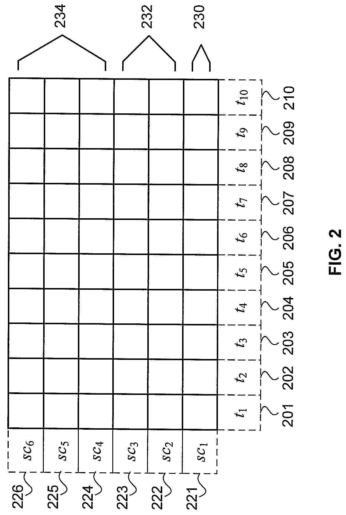
[0010]Each optical carrier is partitioned into a set of orthogonal frequency division multiplex subcarriers and a set of time slots. Bandwidth may be efficiently and dynamically allocated by assigning specific sets of subcarriers and time slots to different data packets.

Problems solved by technology

FTTP, however, often requires installation of equipment in outside plant, which is typically exposed to uncontrolled environments.
Supplying reliable power to outside plant is also more difficult and expensive than supplying reliable power to a central office, for example.
Furthermore, since communications links are geographically dispersed over many customers, management of the distribution plant is more difficult than management of the infrastructure of a central office, for example.
Since each architecture and each protocol may require custom hardware and software, the capital expense and operating costs for initial development and for subsequent network operations, administration, maintenance, and provisioning (OAM&P) may be extremely high.

Method used


Image

  • Orthogonal Frequency Division Multiple Access Based Virtual Passive Optical Network (VPON)
  • Orthogonal Frequency Division Multiple Access Based Virtual Passive Optical Network (VPON)
  • Orthogonal Frequency Division Multiple Access Based Virtual Passive Optical Network (VPON)

Examples


Embodiment Construction

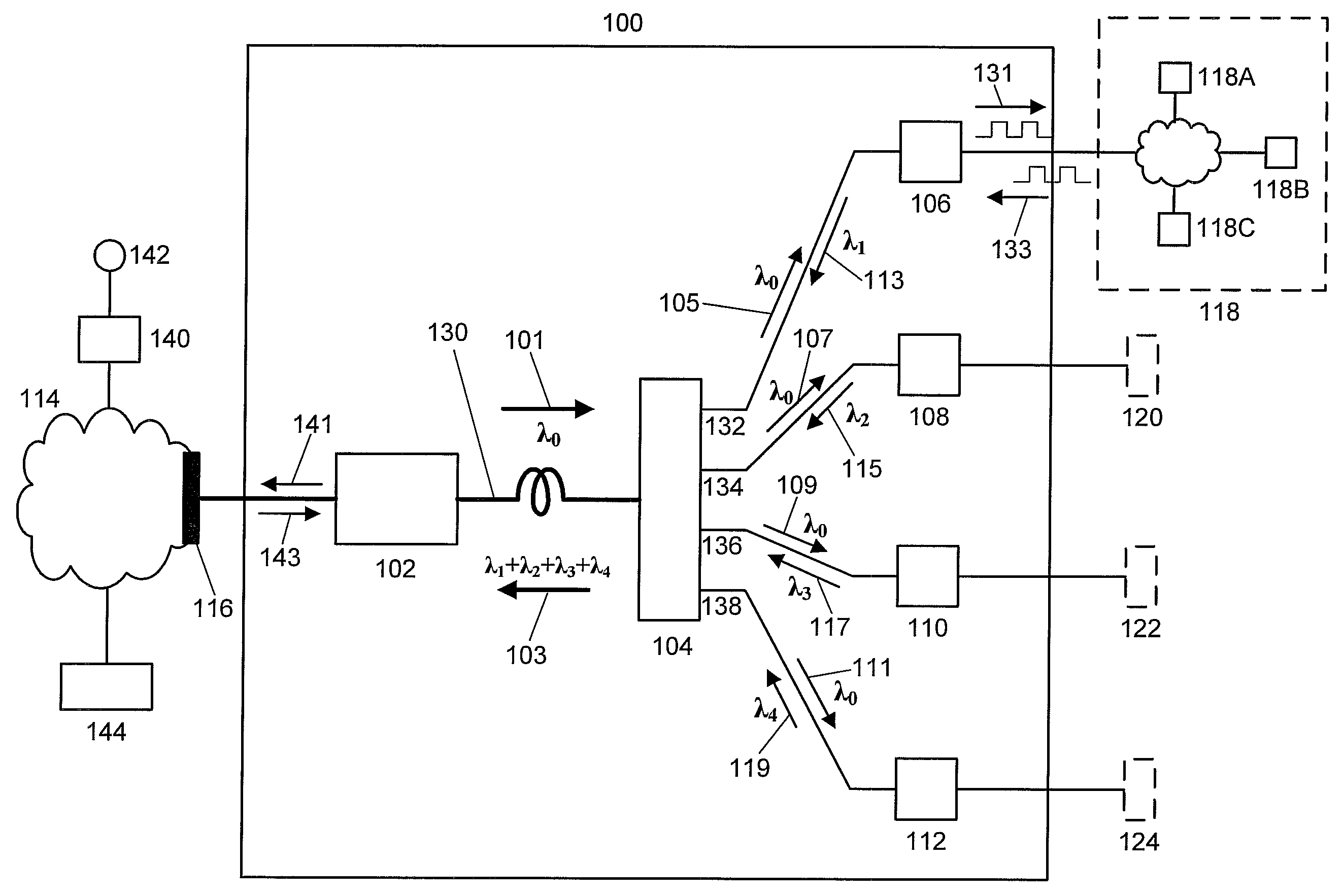
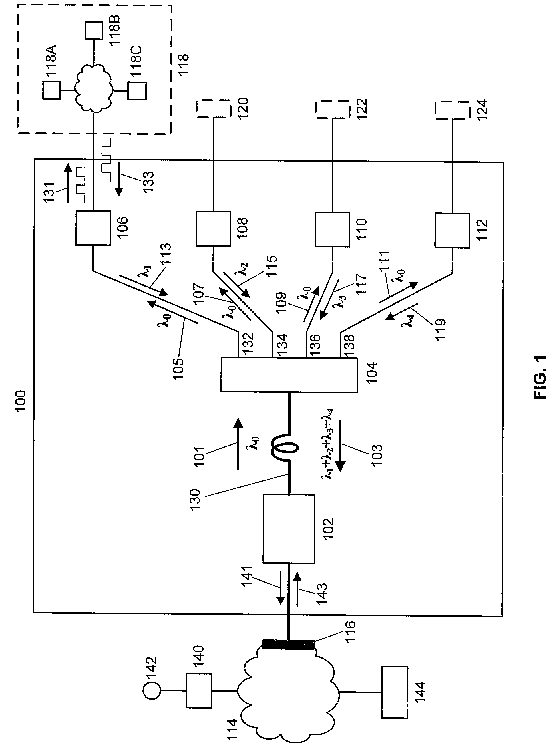
[0016]Multiple network architectures and multiple network protocols are evolving for passive optical networks (PONs). The operating environment of local access and premises networks are less defined than that of core networks. Low costs are also a more significant factor for PONs than for core networks, since the cost of a PON is amortized over fewer customers than that of a core network. FIG. 1 shows a high-level schematic of a PON, referred to as a virtual passive optical network (VPON) 100. It is referred to as a virtual passive optical network because it may flexibly and dynamically adapt to and simultaneously support multiple passive optical network protocols via software. VPON 100 may support a diverse range of users and applications without major changes in hardware.

[0017]In the embodiment shown in FIG. 1, VPON 100 includes optical line terminal OLT 102, passive remote node RN 104, and optical network units ONU1106-ONU4112. OLT 102 is typically located in a central office; RN...


PUM


Abstract

Various types of passive optical networks operate simultaneously in one passive optical network system comprising an optical line terminal, a passive remote node, and multiple optical network units. Downstream data is orthogonal frequency division multiplexed onto a single wavelength optical carrier transmitted on a primary downstream optical beam from the optical line terminal to a splitter in the passive remote node. The primary downstream optical beam is split into multiple secondary downstream optical beams; each is transmitted to a specific optical network unit. Upstream data is orthogonal frequency division multiplexed onto a single wavelength optical carrier transmitted on a secondary upstream optical beam from each optical network unit to a coupler in the passive remote node. The upstream wavelength for each optical network unit is different. The wavelength division multiplexed optical beam is transmitted from the passive remote node to a parallel signal detector in the optical line terminal.

Description

[0001]This application claims the benefit of U.S. Provisional Application No. 60 / 978,284 filed Oct. 8, 2007, which is incorporated herein by reference.BACKGROUND OF THE INVENTION[0002]The present invention relates generally to fiber optic transmission (transport) systems, and more particularly to orthogonal frequency division multiple access based virtual passive optical networks.[0003]Fiber optics is a reliable technology for high-speed packet data transmission in telecommunications networks. It has been extensively deployed in core networks, in which the network equipment is typically installed in controlled environments. Environmental variables, such as temperature, humidity, vibration, and shock, are regulated according to industry standards. In addition, these installations typically have reliable power sources, including battery backup.[0004]Multimedia services (data, voice, and video) are increasingly being provided over packet data networks. These services require high-speed...

Claims


Application Information

Patent Timeline
Patent Type & Authority Applications(United States)
IPC IPC(8): H04J14/02H04B10/27H04B10/272
CPCH04J14/0282
Inventor WEI, WEIWANG, TING
Owner NEC LAB AMERICA
Learn More