
Achery release aid

Inactive Publication Date: 2009-04-16
GRAVES NATHANIEL DAVID
View PDF17 Cites 21 Cited by
  • Summary
  • Abstract
  • Description
  • Claims
  • Application Information

AI Technical Summary

Benefits of technology

[0011]The present invention provides advantages and alternatives over the prior art by providing, an archery release aid providing a practical means for increasing the ability of an archer to pull a strong bow, reducing muscle strain and increasing stability while aiming and releasing the arrow.
[0012]According to a further aspect of the present invention, there is provided an archery release aid allowing an archer to draw a bow with reduced effort and greater ease and greater accuracy in holding the draw and in releasing the arrow comprising in cooperative combination: a substantially rigid cuff generally conforming to a portion of the archer's upper arm having a pair of adjustable mounting straps allowing attaching of said substantially rigid cuff to the upper arm of an archer; a pair of sling straps attached at their distal ends by attaching means to said substantially rigid cuff, and attached together at their proximal; a connecting strap having a first end attached to said attached proximal ends of straps and a second end capable of connecting to an arrow trigger release device and secured at a desired position by a securing means; a securing means for securing said connecting strap second end along said connecting strap at a desired point; and a retaining strap thereby allowing an archer to draw a bow and knocked arrow using the upper arm and back muscles while eliminating muscle tension in the forearm, wrist, and hand.
[0013]According to yet another aspect of the present invention, there is provided an archery release aid allowing an archer to draw a bow with reduced effort and greater ease and greater accuracy in holding the draw and in releasing the arrow comprising in cooperative combination: a substantially rigid cuff generally conforming to a portion of the archer's upper arm having a pair of adjustable mounting straps allowing attaching of said substantially rigid cuff to the upper arm of an archer; a sling strap having two ends passing around the circumference and attached to said substantially rigid cuff, and attached together at said two ends; a connecting strap having a first end attached to said attached two ends of said sling strap and a second end capable of connecting to an arrow trigger release device and secured at a desired position by a securing means; a securing means for securing said connecting strap second end along said connecting strap at a desired point; and a retaining strap thereby allowing an archer to draw a bow and knocked arrow using the upper arm and back muscles while eliminating muscle tension in the forearm, wrist, and hand. It is to be appreciated that in this preferred embodiment straps 6 and 7 may be formed from a single length of strap material, preferably flat nylon webbing.
[0014]By leaving most of the arm in a relaxed condition while drawing, holding, and triggering the bow, archer fatigue is decreased and the user has more stability in controlling arrow release, thereby increasing arrow placement accuracy. The archer may choose to use any of a number of available release mechanisms and, regardless of which style is used, will experience better control during the trigger pull since the hand is in a more relaxed condition than it would be without using this sling.
[0016]The present invention thus advantageously provides an archery release aid that reduces the effort required to draw the bow and further realizes the advantage of not putting the finger, hand, wrist, and forearm joints and muscles under tension in drawing the bow.

Problems solved by technology

No practical means of providing mechanical leverage for a standard bow has emerged as the pull of the bow-string is transmitted along the bones of the forearm through the joint of the elbow.
But, the hand or wrist remains under tension with these devices, somewhat constraining motion of the finger used to release the trigger.
None of the devices provide a practical aid to archers in pulling a bowstring during normal archery shooting.
Some people with damaged hands or arms cannot use a normal archery bow.

Method used


Image

  • Achery release aid
  • Achery release aid
  • Achery release aid

Examples


Embodiment Construction

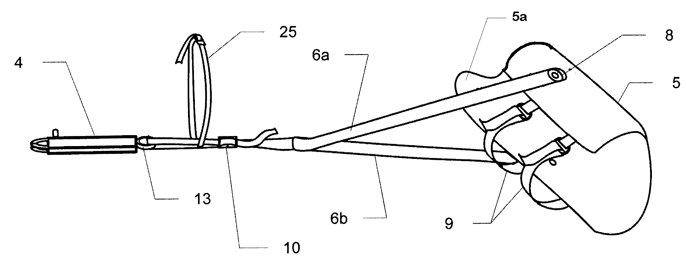
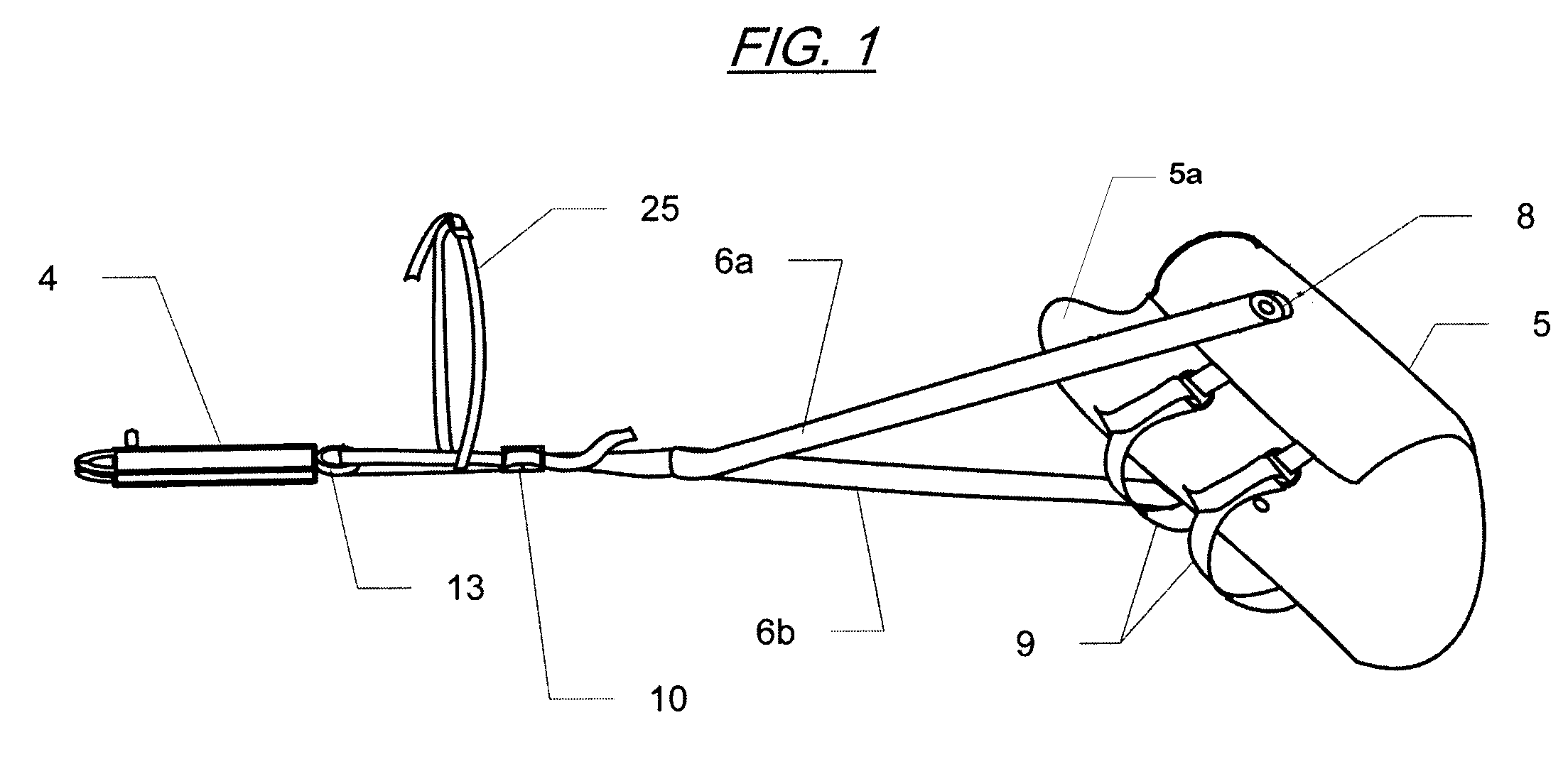
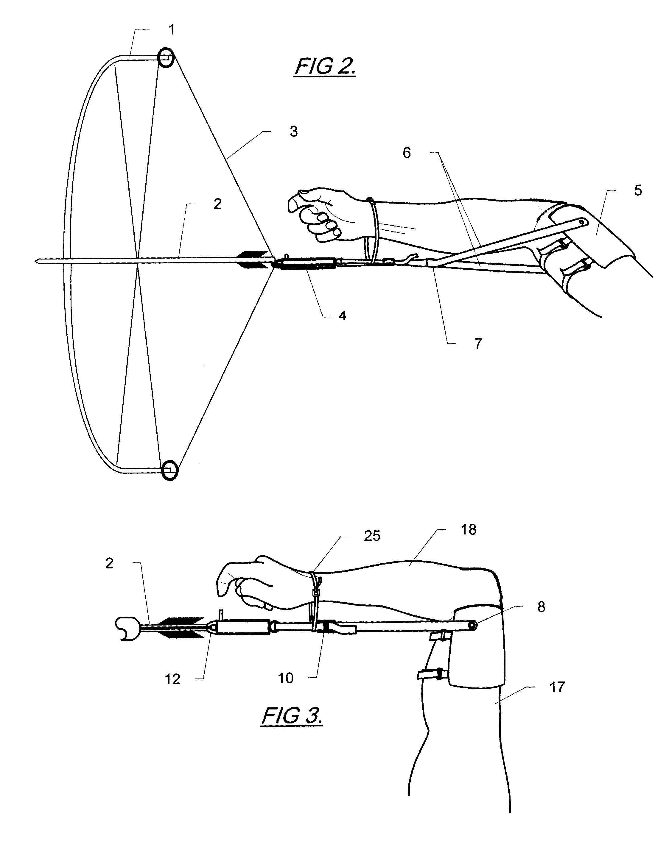
[0025]Reference will now be made to the drawings, wherein to the extent possible like reference numerals are utilized to designate like components throughout the various views. Referring to FIG. 1, which presents a perspective view of one preferred embodiment of the present invention comprising a substantially rigid cuff 5 having an elbow support 5a, and further having a pair of attachment straps 9 for securing said substantially rigid cuff 5 to the upper arm of an archer. Also shown are a pair of straps 6a and 6b forming a sling with substantially rigid cuff 5, having their distal ends moveably fixedly attached to said substantially rigid cuff 5 by means of attaching means 8 and having their proximal ends fixedly attached together and to strap 7 a single strap suitable for passing through the rear attachment point 13 of a known arrow trigger release 4. Strap 7 returning to pass through an adjusting securing means 10 allowing for fixing the length of the archery release aid to the a...


PUM


Abstract

An archery release aid for drawing the string of a bow using a substantially rigid cuff mounted on an archer's upper arm above the elbow comprising a substantially rigid cuff, a strap to transmit pulling force, and a means for attaching said archery release aid to known bow-string arrow trigger release devices. This archery release aid increases pull-force by relying on strength from the archer's upper arm and back instead of the lower arm and hand, and increases stability and shot accuracy by freeing the archer's hand and wrist from tension during release. Moving the point of pull above the elbow provides better leverage to the archer that allows him to pull a bow more easily or to pull a stronger bow than he would otherwise be able to pull. As the wrist is freed from tension the archer is better able to control release of the trigger, resulting in better consistency and accuracy of arrow placement.

Description

BACKGROUND OF THE INVENTION[0001]1. Field of the Invention[0002]The present invention relates to accessories for use with an archery bow, particularly to those devices which aid in pulling the string of a bow, and more particularly to pulling devices operated directly by the human arm.[0003]2. Description of the Related Art[0004]Over history many improvements have been made in the design of archery bows and accessories for use with bows to increase arrow speed and to improve accuracy of arrow placement.[0005]In recent years the use of compound bows designed with cables and pulleys and constructed of high strength composite materials has become common. During the act of drawing, the pull-force of these bows starts out very high until the bow is almost fully-pulled. Then, as the bow approaches the fully-pulled position, a series of mechanical cams reduces the pull force to partially relieve stress in the arm of the archer. With a compound bow an archer may be able to pull a stronger b...

Claims


Application Information

Patent Timeline
IPC IPC(8): F41B5/18
CPCF41B5/1469
Inventor GRAVES, NATHANIEL DAVID
Owner GRAVES NATHANIEL DAVID
Learn More