Therapeutic/diagnostic external airway position support (EAPS) device and method

a position support and therapeutic technology, applied in the field of anesthesia delivery, can solve the problems of compromising free respiratory exchange, compromising patient comfort, and compromising the upper airway, etc., and achieves the effects of convenient use on a patient, convenient disposable, and low cos

Inactive Publication Date: 2009-04-16
DERRICK STEVEN J +1
View PDF3 Cites 13 Cited by
  • Summary
  • Abstract
  • Description
  • Claims
  • Application Information

AI Technical Summary

Benefits of technology

[0016]Another object of this invention is to provide an external airway position support device that is easy to use on a patient while sitting, partially reclining, supine or laying lateral to one degree or another, either face up or face down. Another object is to provide an external airway position support that is lightweight and inexpensive to make, use and operate. A still further object is to provide a position support device that is readily disposable after use.
[0017]With the various embodiments of this invention described below, an anesthetist can more efficiently provide patient care during MAC and/or TIVA anesthesia, as this device makes it unnecessary for the anesthetist to continuously perform the required intricate airway maneuvers. Accordingly, several main objects and advantages of the present invention include: (a) not requiring the anesthetist to maintain substantially continuous physical contact with the patient's external airway at all times; (b) allowing the anesthetist less restricted movement around the patient's positioning; (c) freeing up the anesthetist to perform his or her other tasks, including administering medications, procedural observation, monitoring and documentation of respective details and responses; (d) rendering less critical the choreographing of operating room table placement and patient positioning in order to maintain the appropriate force vectors on the external airway during long surgical procedures; (e) preventing the anesthetist's arms, hands and fingers from becoming unnecessarily fatigued or stiff as would otherwise be the case when having to continually provide manual airway support; (f) avoiding the need to induce general anesthesia when local anesthesia would otherwise suffice with supplemental sedation/analgesia thereby alleviating other potential detriments such as sore throat, an increased propensity to nausea/vomiting, and inju

Problems solved by technology

One risk of using the MAC or TIVA anesthetic technique is that an upper airway compromise can, and often does, occur.
And an unattended interference with a free exchange of respiration predisposes patients to a higher incidence of morbidity/mortality.
Because of this diminished tonicity, the upright and balanced position of the jaw and skull are negatively impacted upon while the tongue and soft palate begin to approximate the posterior pharyngeal wall thereby compromising free respiratory exchange.
Other factors, such as the surgical logistics, can make performing the noted airway maneuvers awkward and preclude the anesthetist from more efficiently performing his/her other responsibilities.
Still other disadvantages posed by the necessity to manually prevent airway obstruc

Method used


Image

  • Therapeutic/diagnostic external airway position support (EAPS) device and method
  • Therapeutic/diagnostic external airway position support (EAPS) device and method
  • Therapeutic/diagnostic external airway position support (EAPS) device and method

Examples


third embodiment

[0046]In accompanying FIGS. 11, 12A, 12B and 12C, there is shown EAP device, generally 250, that has an overall circular appearance in top view. Before inflation, device 250 has a somewhat Z-shaped design with a fattened or rounded, central region 251. It may also resemble the symbol for a hurricane on weather maps.

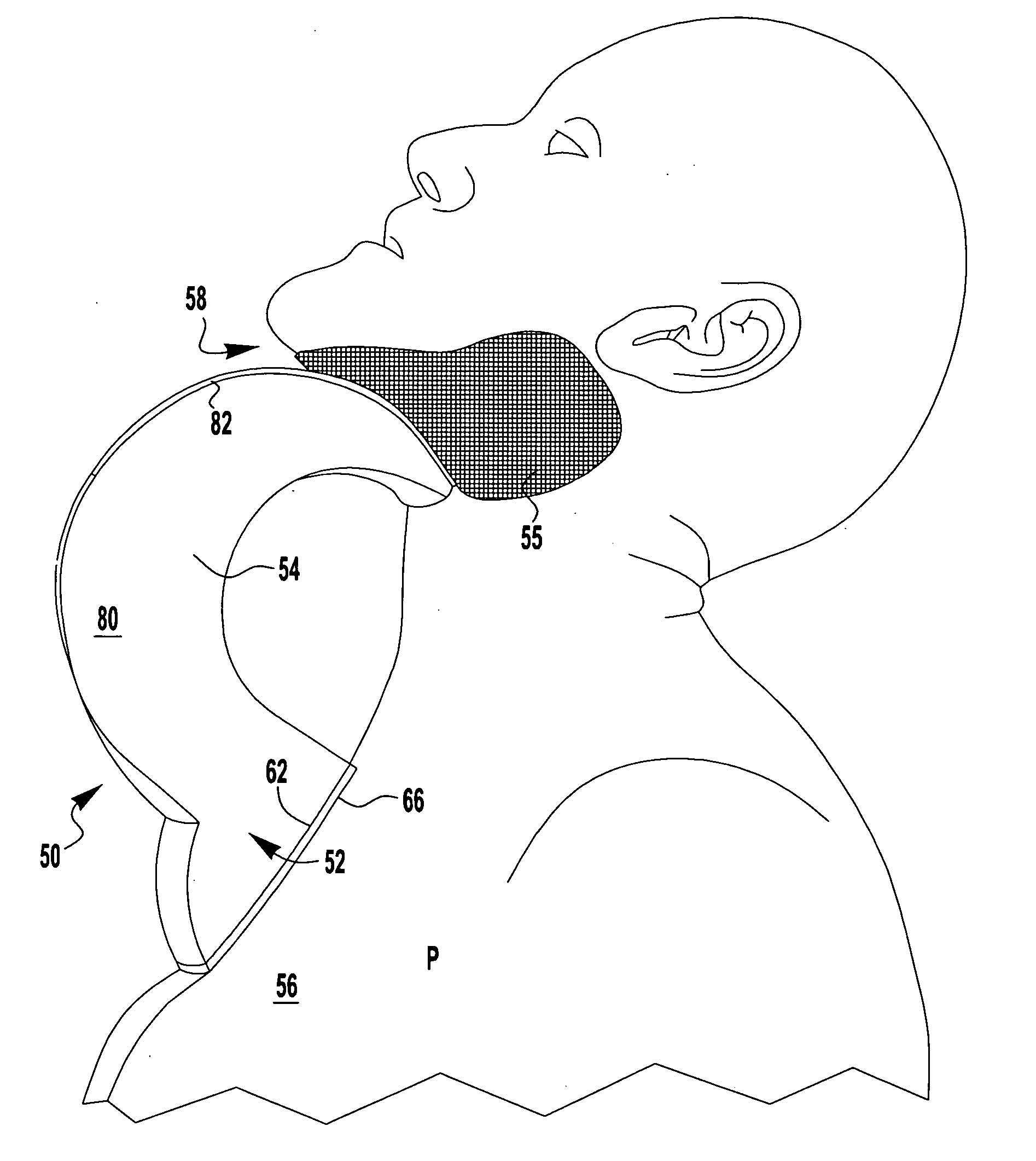
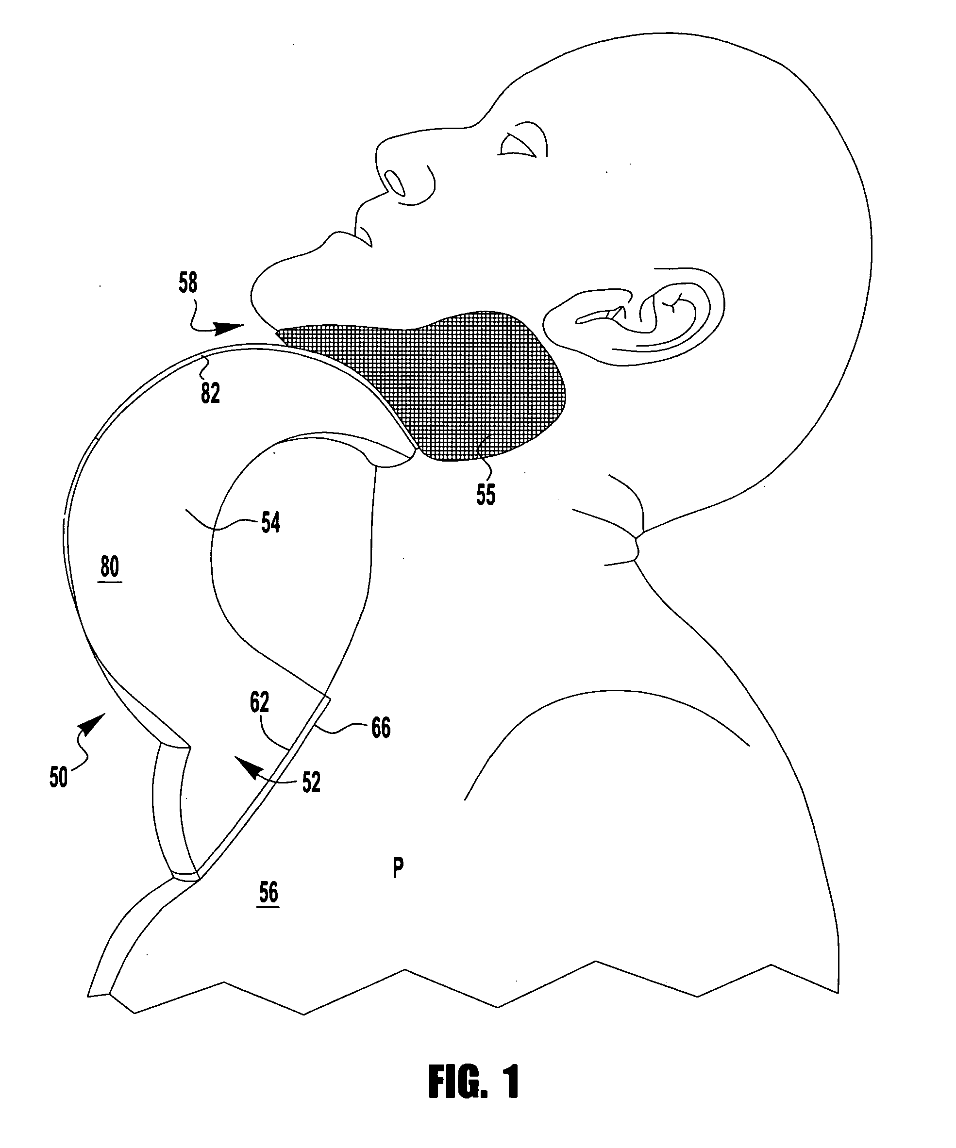
[0047]Device 250 may be made from an inflatable plastic liner preconfigured to have a lowermost chest contacting, or manubrium portion 252 and an upper or top mandibular portion 254 on opposite sides of central region 251. The side edge 255, between front and rear faces to device 250, is contoured to resemble a continuous V-shape. With that configuration, device 250 can serve as a suitable chin-rest when positioned beneath the mandibular region 258 of patient P.

[0048]As shown, both the lower portion 252 and top portion 254 have separate valves, 252v and 254v, respectively. When connected to a pump, gas can or other air supplying means (not shown), each valve causes a ball...

fourth embodiment

[0051]Referring to FIGS. 13 and 14, there is shown a fourth embodiment wherein device 350 has a plurality of chambers 350c that upon inflation will accordion upwardly from a starting position to expand between the patient's upper chest 356 and chin 358. As shown, device 350 is essentially C-shaped, though in the embodiment at FIG. 13, a structural vertical reinforcement 355 gives the device 350 somewhat of a hinged appearance. Regardless, it is preferred that regardless of the number of baffles comprising device 350, they should all be filled (and subsequently deflated) through a single, common valve 350v.

[0052]For illustrative purposes, the lower end of device 350 is provided with a first layer of adhesive 366L for sticking to a patient's manubrium 356 and / or partially about the anterior base of their neck. On the opposite end, the uppermost surface of device 350 has its own adhesive layer 366U for adjoining same to the wearer's chin, or mandibular region 358.

[0053]Any of the fore...


PUM


Abstract

A hands free, external airway position support device for use on a patient undergoing a surgical, therapeutic and/or diagnostic procedure. The device adheres to the patient at the base of his or her chin, jaw or neck so that no wrap around neck or head sling attachment means are required. When installed, the device will extend the patient's neck and maneuver his or her chin upward and outward, away from the base of the neck. As this device will be relatively inexpensive to manufacture and not overly complicated, it can be disposed of after use rather than requiring sterilization for reuse.

Description

CROSS-REFERENCE TO RELATED APPLICATIONS[0001]This application claims priority to U.S. Provisional Application Ser. No. 60 / 999,089, filed on Oct. 16, 2007, the disclosure of which is fully incorporated by reference herein.BACKGROUND OF THE INVENTION[0002]1. Field of the Invention[0003]This invention relates to anesthesia delivery and a device for adjustably supporting the mandibular region of a patient to minimize airway compromises during surgical therapeutic and / or diagnostic procedures. It may also be utilized to assist a practitioner via position support / stabilization during mask ventilation or laryngoscopy. The invention further relates to an improved method for using the aforesaid device during and after certain surgeries.[0004]2. Background of the Invention[0005]Monitored Anesthesia Care (or “MAC” anesthesia) and Total Intravenous Anesthesia (or “TIVA”) are two common means for delivering appropriately titrated doses of drugs to a patient along with anesthetic topicalization o...

Claims


Application Information

Patent Timeline
IPC IPC(8): A61F5/37
CPCA61F5/3707A61B19/203A61B90/14
Inventor DERRICK, STEVEN J.DERRICK, JOYCE A.
Owner DERRICK STEVEN J
Why Eureka
Try Eureka