Method and apparatus for controlling the power output of a radio frequency sealing machine

a technology of radio frequency sealing machine and power output, which is applied in the field of improved methods and methods for welding thermoplastic materials, can solve the problems of inability to directly determine the power output variation of the current or voltage described above, the inability to change the voltage of the incoming voltage of the rf generator, and the capacitor capacitance of the first capacitor

Inactive Publication Date: 2009-04-16
HALL DIELECTRIC MACHINERY
View PDF6 Cites 13 Cited by
  • Summary
  • Abstract
  • Description
  • Claims
  • Application Information

AI Technical Summary

Benefits of technology

[0013]Another object of the present invention is to provide a radio frequency sealing apparatus and method for joining two or more thin thermoplastic sheets along a welded seam having excellent seam integrity.
[0015]Another object of the present invention is to provide a radio frequency sealing apparatus and method for efficiently tuning the RF circuit to generate a predetermined RF frequency for welding two layers of thermoplastic material.

Problems solved by technology

Several problems are associated with the conventional control used in RF welding.
One problem is that the capacitance of the first capacitor can vary because of the varying properties of the dielectric, i.e., air, that is positioned within the gap.
Another problem is that the incoming voltage to the RF generator may vary due to changes in incoming line load.
Another problem associated with conventional control systems of RF welding machines is that the variation of power due to variation of the current or voltage described above can not be directly determined.
Another problem associated with conventional RF welding machines is that the capacitance of the second capacitor may vary during the welding process due to changes of the electrical properties of the thermoplastic that occurs as the thermoplastic melts.

Method used


Image

  • Method and apparatus for controlling the power output of a radio frequency sealing machine
  • Method and apparatus for controlling the power output of a radio frequency sealing machine
  • Method and apparatus for controlling the power output of a radio frequency sealing machine

Examples


Embodiment Construction

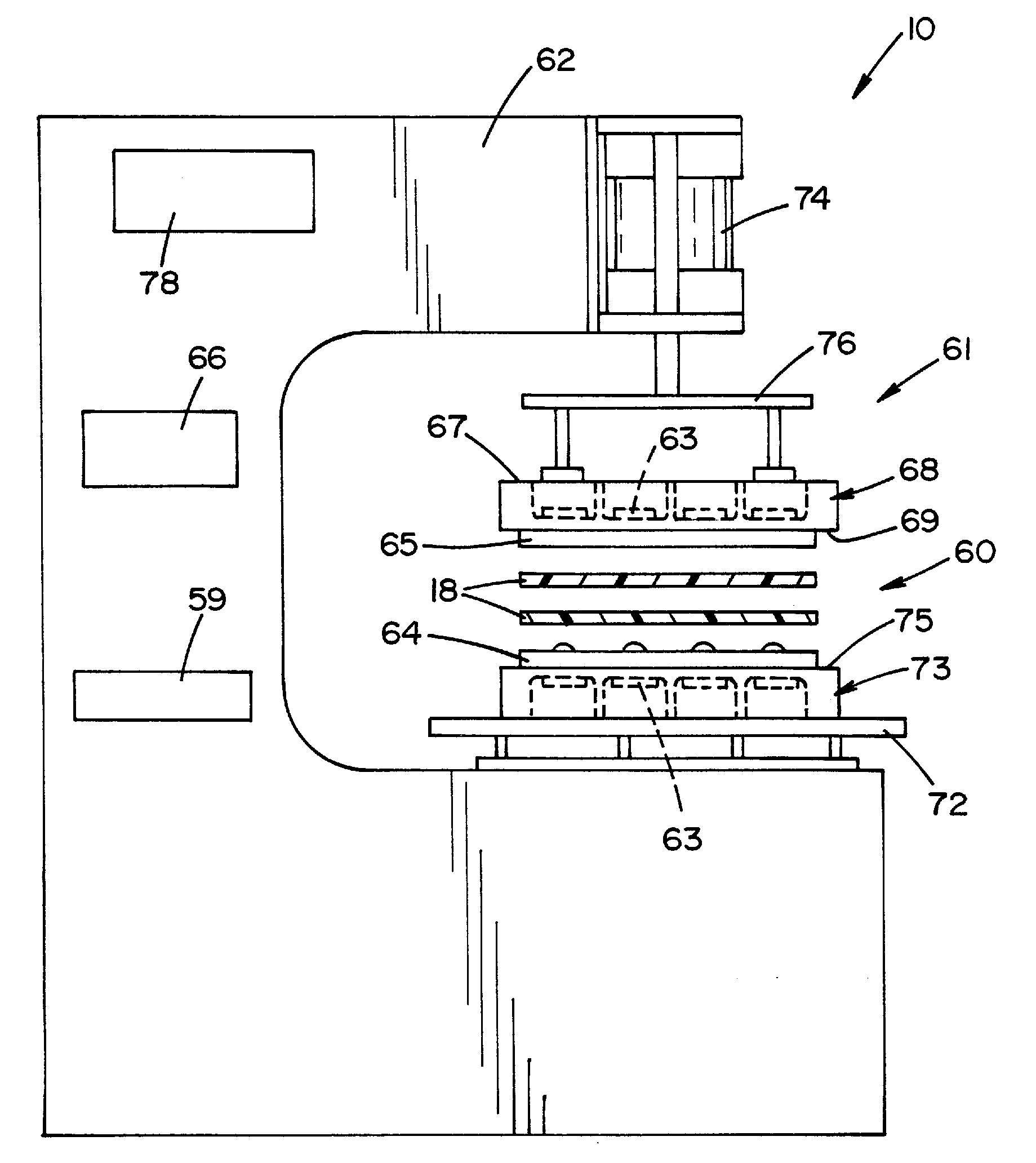
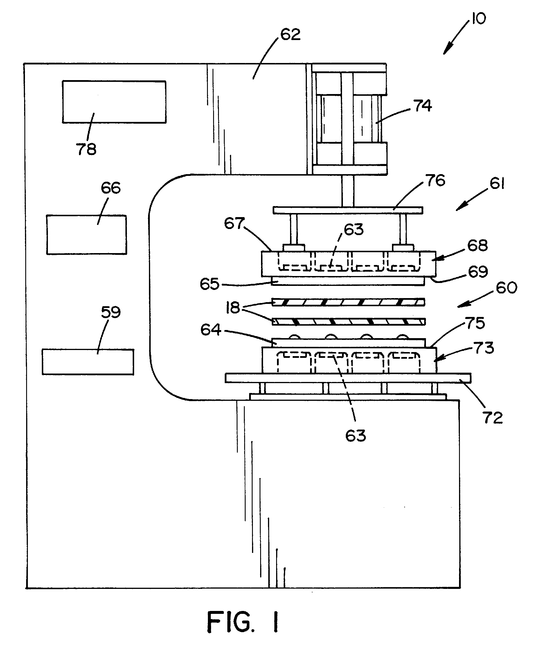
[0032]Referring now to the drawings, an apparatus 10 for joining two or more thin thermoplastic sheets along a welded seam according to the invention is shown in FIG. 1. As used herein, the term “thermoplastic” refers to polyolefins, polyurethanes, vinyls, polyvinyl chlorides (PVCs), and other thermoplastic elastomers. The term “thin thermoplastic sheets” as used herein is not intended to be limited, other than by practicality, to any particular thickness. For example, thermoplastic foils, films, webs, wraps, mats, and laminates are equally applicable to the apparatus and method of the invention. The sheets may be similar or dissimilar thermoplastic materials. However, for the purpose of describing the preferred embodiments disclosed herein, the sheets are the same thermoplastic material, namely a polyolefin such as polypropylene.

[0033]As best shown in FIG. 1, the apparatus 10 includes a welding assembly 60. Welding assembly 60 includes a lower platen 73 and an upper platen 68. Uppe...


PUM

PropertyMeasurementUnit
electrical voltageaaaaaaaaaa
electrical propertyaaaaaaaaaa
energyaaaaaaaaaa

Abstract

The present invention provides a radio frequency welding apparatus for joining multiple layers of thermoplastic materials. The apparatus includes an electrical voltage source that is electrically connected to a radio frequency energy generator. The apparatus also includes a first die and a second die that are configured to form a tooling capacitor when thermoplastic sheets to be welded are positioned between them. The tooling capacitor is electrically connected to the radio frequency energy generator and the dielectric includes a thermoplastic sheet. A processor is electrically connected to the voltage source and is configured to monitor an electrical property applied to the electric circuit and vary voltage supplied to the radio frequency generator such that the electrical property approaches a predetermined value. The radio frequency energy generator is configured to provide energy to the tooling capacitor such the energy can be controlled as the voltage is controlled.

Description

CLAIM OF PRIORITY[0001]The present application claims priority from provisional U.S. Patent Application No. 60 / 980,289 filed on Oct. 16, 2007 which is incorporated herein by reference.FIELD OF THE INVENTION[0002]The present invention relates to an improved apparatus and method for welding thermoplastic materials, and more particularly to an apparatus and a method for joining two or more thin sheets of thermoplastic materials along a welded seam.BACKGROUND OF THE INVENTION[0003]Radio Frequency (RF) welding, also known as RF heat sealing, high frequency sealing, and dielectric heat sealing, is used to produce many types of products by welding together thin thermoplastic sheets. The thermoplastic sheets can be formed of vinyl, polyvinyl chloride (PVC), and polyurethane. Many products can be produced with RF welding including medical products such as blood bags, catheters, and compression sleeves. RF welding can be used to form many different structures including interior welded seams, ...

Claims


Application Information

Patent Timeline
Patent Type & Authority Applications(United States)
IPC IPC(8): B32B37/06
CPCB29C65/04B29C66/45B29K2021/00B29K2021/003H05B6/62B29K2027/06B29K2075/00B29K2101/12H05B6/50B29K2023/00B29C66/8322B29C66/1122B29C66/73921B29C66/91313B29C66/91315B29C66/91653B29C66/71B29C65/18B29C65/72B29C66/91645B29K2023/12
Inventor HALL, WILLIAM ALFREDHALL, PATRICK JOHN
Owner HALL DIELECTRIC MACHINERY
Why Eureka
Try Eureka