Circuit board and method of manufacturing the same

a technology of circuit boards and manufacturing methods, applied in the field of circuit boards, can solve the problems of reducing the advantage of having a low thermal expansion coefficient formed on the core substrate, limiting the density with which the pth can be formed, and reducing the advantages of circuit boards. forming and reducing the cost of manufacturing, the effect of simplifying the construction and manufacturing process of circuit boards

Active Publication Date: 2009-04-16
SHINKO ELECTRIC IND CO LTD
View PDF11 Cites 22 Cited by
  • Summary
  • Abstract
  • Description
  • Claims
  • Application Information

AI Technical Summary

Benefits of technology

[0022]With the circuit board and method of manufacturing a circuit board according to the present invention, by constructing the prepregs that form the core portion of a core substrate so as to include first fibers that conduct electricity and second fibers that do not conduct electricity and so that the nonconductive second fibers are disposed at positions where plated through holes will pass through, it is possible to dispose the PTH so as to avoid electrical shorting with the first fibers. By doing so, it is possible to dispose the PTH with a fine pitch and to simplify the construction and the manufacturing process of a circuit board. Also, by appropriately combining the first fibers and the second fibers, it is possible to improve the characteristics of a circuit board.

Problems solved by technology

However, with a layout where preliminary holes are formed in the core substrate and the PTH are formed so as to pass through the preliminary holes, since the preliminary holes have a larger diameter than the PTH, compared to a construction where PTH are simply formed in the core substrate, there is an increase in the layout spacing between the PTH, which limits the density with which the PTH can be formed.
Also, if the preliminary holes are filled with an insulating resin, there is an effect whereby the thermal expansion coefficient of the core substrate is increased, and for a circuit board equipped with a core portion made of carbon fibers, this reduces the advantage of having the core substrate formed with a low thermal expansion coefficient.

Method used


Image

  • Circuit board and method of manufacturing the same
  • Circuit board and method of manufacturing the same
  • Circuit board and method of manufacturing the same

Examples


Embodiment Construction

Method of Manufacturing a Circuit Board

[0029]One embodiment of a method of manufacturing a circuit board according to the present invention will now be described.

[0030]In the method of manufacturing a circuit board according to the present embodiment, a core substrate with a core portion made of carbon fiber reinforced plastic (CFRP) is used.

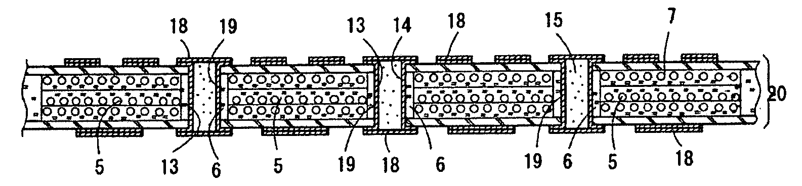
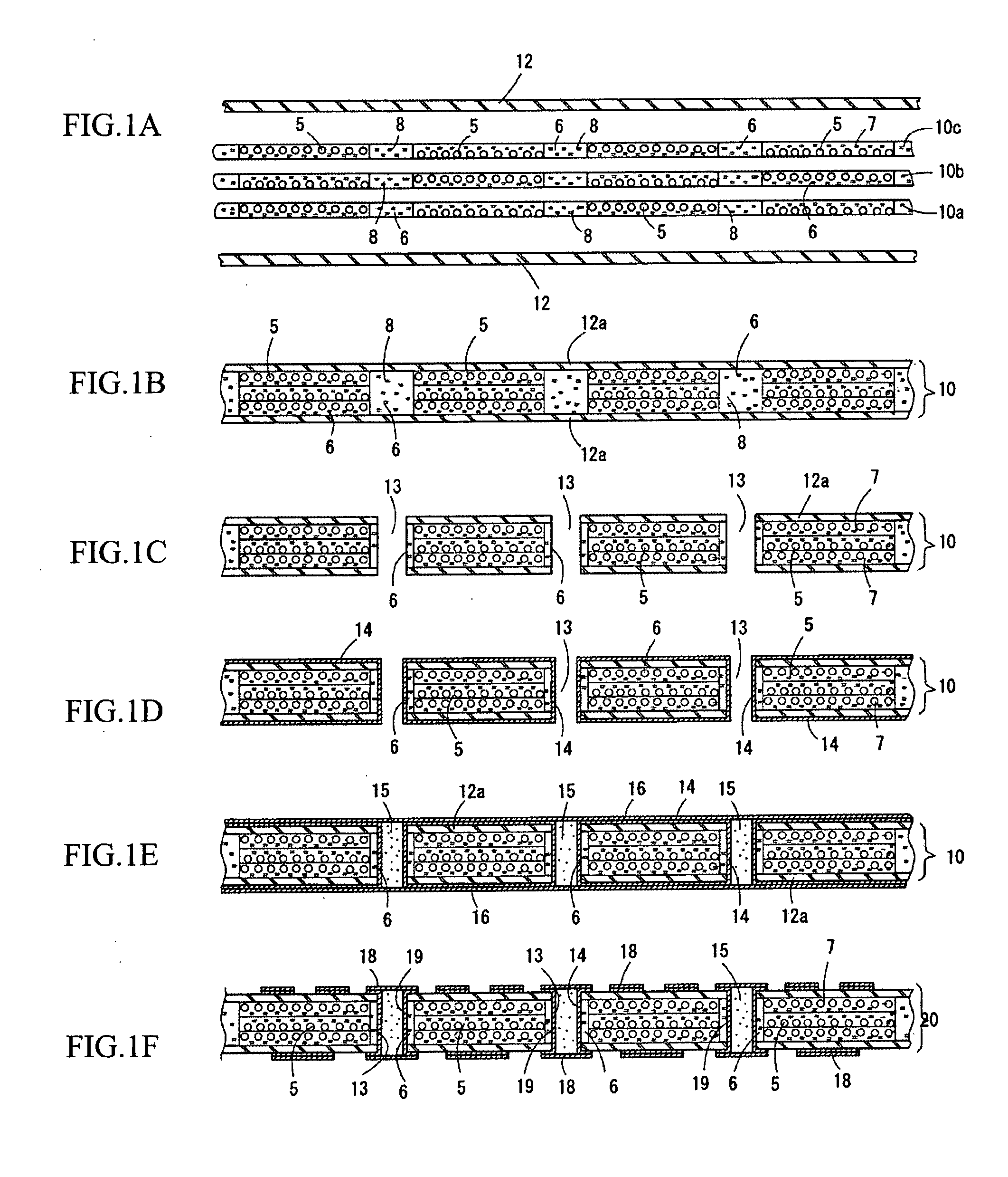
[0031]FIGS. 1A to 1F show the manufacturing steps up to the formation of a core substrate 20 with a core portion 10 made of CFRP.

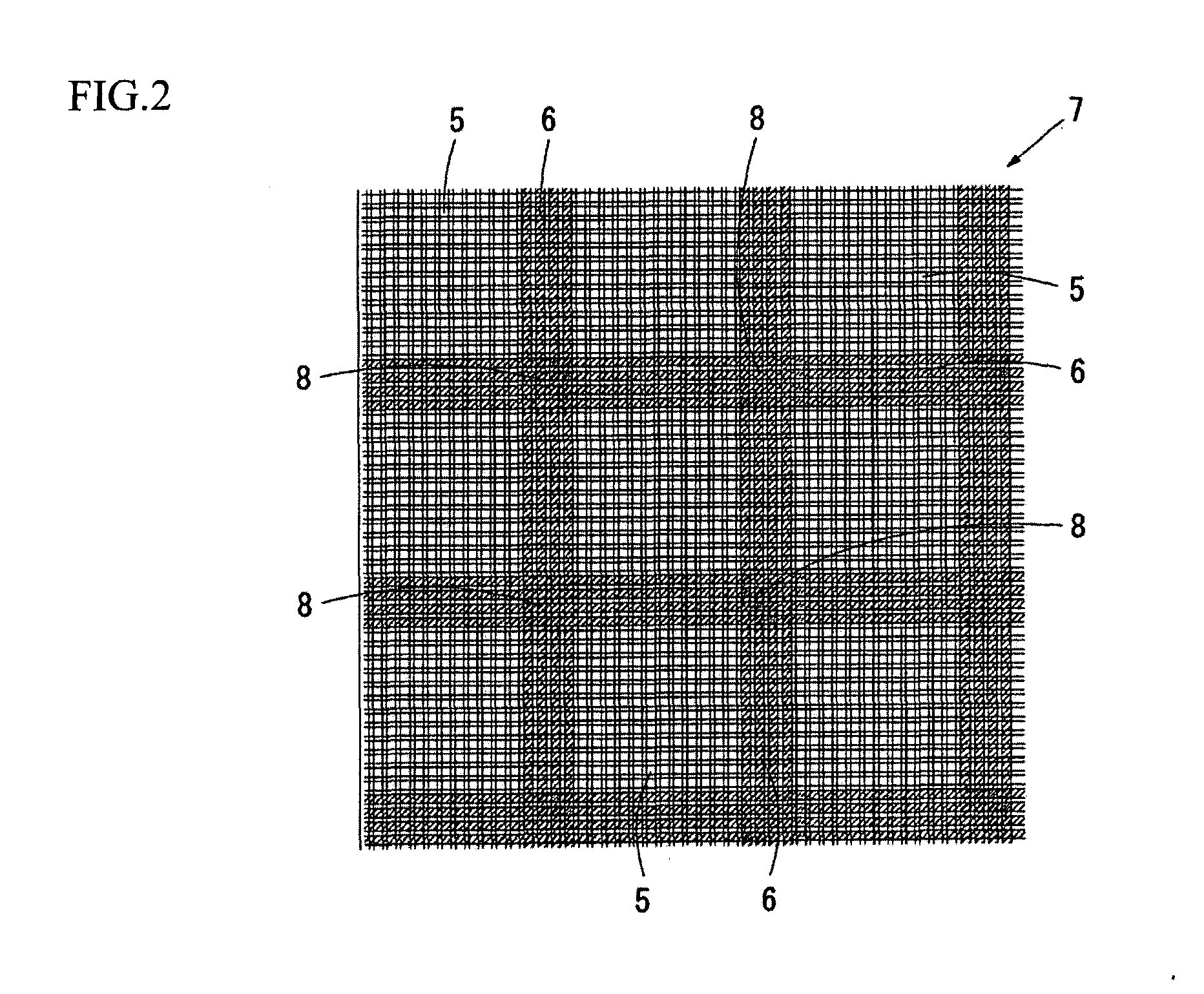
[0032]FIG. 1A shows a state where prepregs 10a, 10b, and 10c that include carbon fiber and electrically insulating prepregs 12 that include a filler such as alumina or silica to adjust the thermal expansion coefficient have been positioned relative to one another in readiness for thermocompression bonding.

[0033]Although three prepregs 10a, 10b, and 10c are placed on top of each other to form the core portion 10 in the present embodiment, the number of prepregs used to construct the core portion 10 may be selected as ap...


PUM

PropertyMeasurementUnit
angleaaaaaaaaaa
conductiveaaaaaaaaaa
thermal expansion coefficientaaaaaaaaaa

Abstract

A circuit board has plated through holes which are laid out with a fine pitch and meets requirements relating to characteristics such as the thermal expansion coefficient of the circuit board. A method of manufacturing a circuit board includes: a step of forming a core portion by thermal compression bonding prepregs which include first fibers that conduct electricity and second fibers that do not conduct electricity, which have the second fibers disposed at positions where plated through holes will pass through, and which are impregnated with resin; a step of forming through holes at positions in the core portion where the second fibers are disposed; and a step of forming a conductive layer on inner surfaces of the through holes to form plated through holes at positions that do not interfere with the first fibers and thereby produce a core substrate.

Description

BACKGROUND OF THE INVENTION[0001]1. Field of the Invention[0002]The present invention relates to a circuit board and a method of manufacturing the same, and in more detail to a circuit board with a core substrate, a method of manufacturing the same, a semiconductor device that uses a circuit board, and a prepreg used in a circuit board.[0003]2. Related Art[0004]Circuit boards used to mount semiconductor elements include boards with a core substrate made of carbon fiber reinforced plastic (CFRP). A core substrate made of CFRP has a low thermal expansion coefficient compared to a conventional core substrate made of a glass epoxy substrate. A circuit board that uses a CFRP core substrate can be manufactured so that the thermal expansion coefficient matches the thermal expansion coefficient of a semiconductor element, which is effective in avoiding thermal stress that is produced between the semiconductor element and the circuit board.[0005]A circuit board is formed by laminating wiring...

Claims


Application Information

Patent Timeline
Patent Type & Authority Applications(United States)
IPC IPC(8): H01R12/04H01K3/10
CPCH05K1/0366H05K3/445H05K3/4641H05K2201/0278H05K2201/029Y10T29/49126Y10T29/49155Y10T29/49165Y10T29/49156Y10T29/4913Y10T29/49128H05K2201/0323
Inventor YOKOUCHI, KISHIOYOSHIMURA, HIDEAKIFUKASE, KATSUYA
Owner SHINKO ELECTRIC IND CO LTD
Why Eureka
Try Eureka