Piezoelectric Actuator

a technology of actuators and actuators, applied in piezoelectric/electrostrictive/magnetostrictive devices, piezoelectric/electrostriction/magnetostriction machines, electrical equipment, etc., can solve problems such as the risk of electrical shorting between the side edges of internal electrodes of opposite polarities, and achieve the effects of improving the reliability of the actuator, protecting the environment and from contamination, and increasing the robustness against fuel

Inactive Publication Date: 2010-10-21
DELPHI INT OPERATIONS LUXEMBOURG S A R L
View PDF9 Cites 9 Cited by
  • Summary
  • Abstract
  • Description
  • Claims
  • Application Information

AI Technical Summary

Benefits of technology

[0015]Advantageously, the invention provides an effective passivation function of the surface of the actuator, protection against the ...

Problems solved by technology

The high electrical field applied to the elements causes a risk of electrica...

Method used


Image

  • Piezoelectric Actuator
  • Piezoelectric Actuator
  • Piezoelectric Actuator

Examples


Embodiment Construction

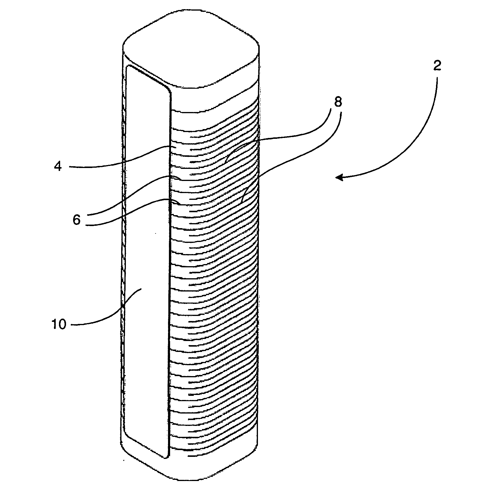
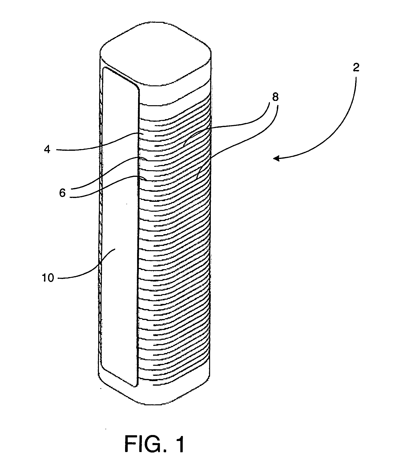
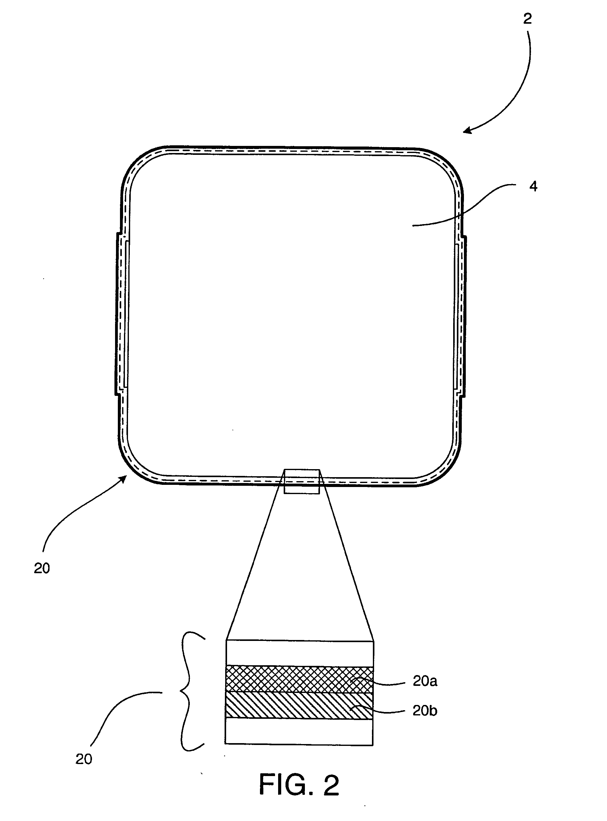
[0020]In FIG. 2, in order to protect the actuator 2 from the aggressive chemical environment in which it is to be used, the actuator 2 is provided with a passivation means 20 that is arranged to cover substantially the entire surface of the actuator 2.

[0021]The passivation means 20 comprises two layers: an adhesive layer 20a and a protective barrier or ‘passivation’ layer 20b. The adhesive layer 20a is provided immediately adjacent the surface of the actuator 2, and intermediate the barrier layer 20b. The bonding layer 20a provides a means to fix the barrier layer 20b to the actuator 2 and is preferably in the form of an epoxy glue having a high temperature stability and low ionic content so as to be electrically resistive. For example, the adhesive layer 20a may be composed of a silicone, fluorosilicone, acrylic or epoxy based adhesive. The adhesive layer thickness should be less than about 100 μm.

[0022]During construction of the actuator 2, the adhesive layer 20a may be applied ei...


PUM


Abstract

A piezoelectric actuator (2) comprising a stack of one or more piezoelectric elements (4) defining an external surface, and passivation means (20) applied to the external surface of the stack, wherein the passivation means (20) includes a self-supporting polyimide material (20b) (e.g. in the form of a layer, film or membrane).

Description

TECHNICAL FIELD[0001]The invention relates to a piezoelectric actuator suitable for use in a fuel injector of an internal combustion engine. In particular, the invention relates to a means for encapsulating the piezoelectric actuator to protect it against damage.BACKGROUND TO THE INVENTION[0002]Known piezoelectric fuel injectors typically employ piezoelectric actuators made from a stack of a plurality of piezoelectric ceramic discs or plates each connected to an electrode for electrically charging and discharging the stack. The actuator is mechanically arranged for opening and closing an injector valve having a valve needle to meter fuel injected into the engine. In some injectors, the piezoelectric actuator is located in a chamber containing fuel—usually diesel, biodiesel or gasoline—pressurised up to 2000 bar. An example of a piezoelectric fuel injector is disclosed in the applicant's U.S. Pat. No. 6,520,423, which utilises a hydraulic coupling arrangement to lift the valve needle...

Claims


Application Information

Patent Timeline
IPC IPC(8): H01L41/053H01L41/083
CPCH01L41/083H01L41/0533H10N30/883H10N30/50
Inventor KIEFER, JOACHIM R.VENDULET, JOACHIM
Owner DELPHI INT OPERATIONS LUXEMBOURG S A R L
Why Eureka
Try Eureka