
Power generation system

a power generation system and power generation technology, applied in the direction of electric generator control, machines/engines, mechanical equipment, etc., can solve the problems of system to have a leading power factor, system instability, and power factor may not be adequately compensated in this way

Active Publication Date: 2009-04-16
CUMMINS GENERATOR TECH LTD
View PDF15 Cites 21 Cited by
  • Summary
  • Abstract
  • Description
  • Claims
  • Application Information

AI Technical Summary

Benefits of technology

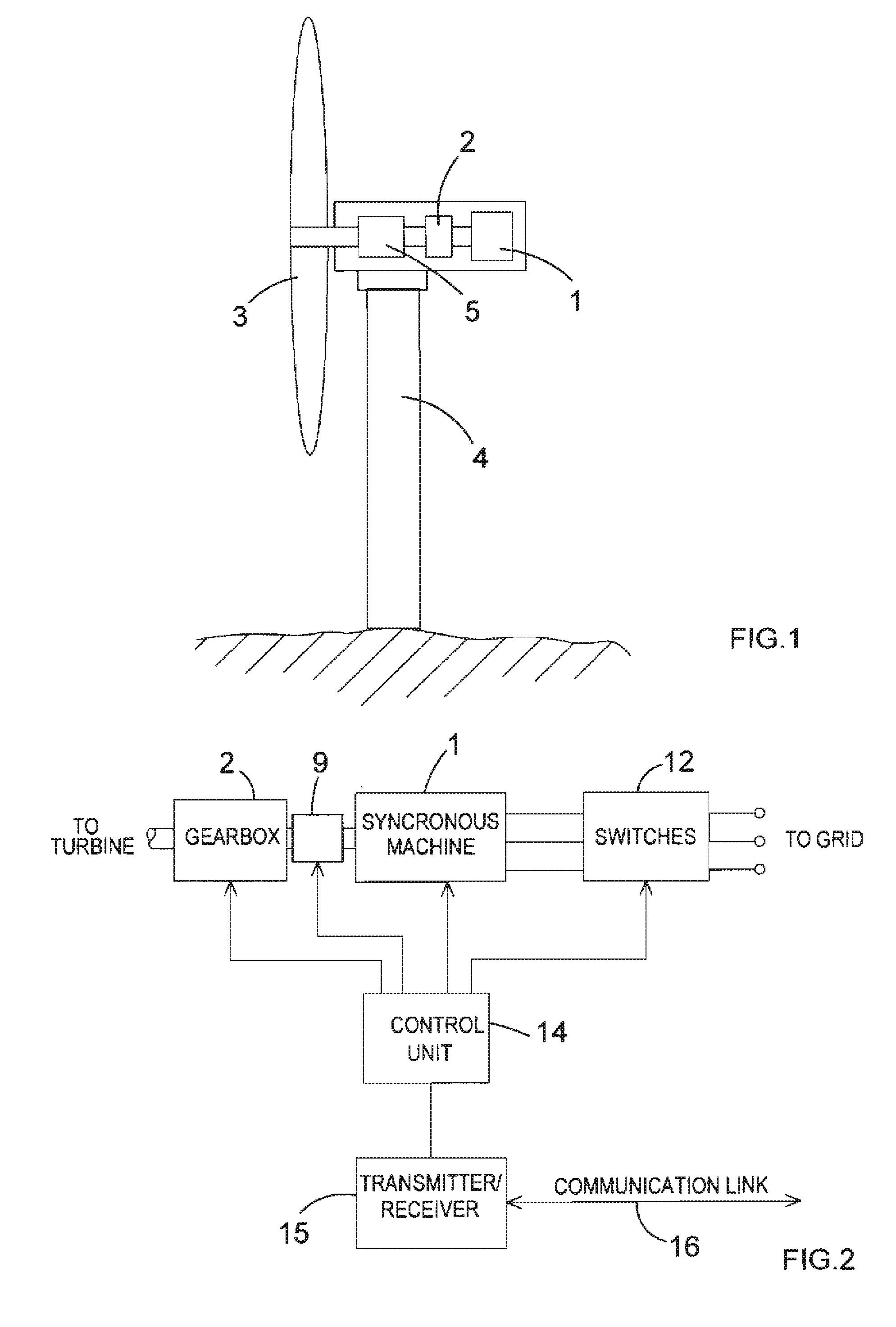
[0012]By providing a power generation system having a synchronous machine which is selectively operable as a synchronous condenser, it may be possible to adjust a parameter of the grid, such as power factor or voltage. The adjustment may be carried out to a large extent using equipment which is already available, thereby providing an economical solution to the problem of adjusting power factor and other parameters. The adjustment may take place close to the point of power generation. This may allow the continued use of transmission lines which might otherwise need to be switched out of the system. Thus the present invention may allow more efficient use of energy sources such as alternative energy sources.
[0013]Preferably, when the system is in the second mode, the synchronous machine is arranged to adjust the power factor and / or the voltage of the electrical grid. Amongst other things, this may help to compensate for the capacitance effect of a transmission line.
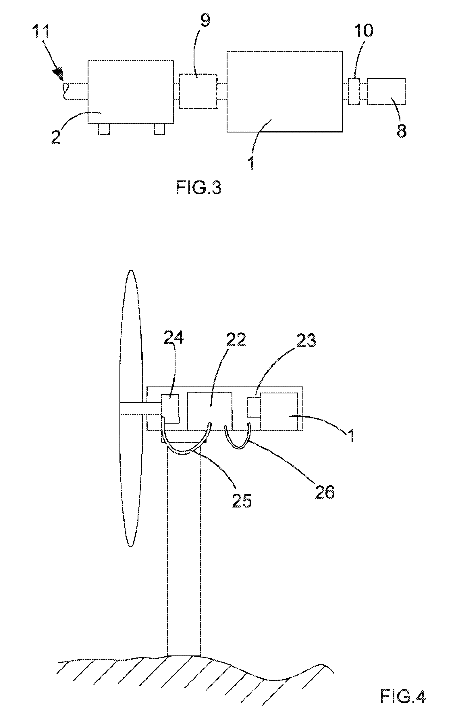
[0024]The variable drive system may comprise, for example, a variable speed gearbox. Such a gearbox may have a single stage, or two, three or more stages in order to increase the range of speeds. Alternatively or in addition the variable drive system may comprise a hydraulic drive. This may have the advantage of isolating the prime mover from the synchronous machine.

Problems solved by technology

Alternative energy sources are often located at long distances from centres of population, and may require long transmission lines to supply power to areas where it is needed.
This in turn may cause the system to have a leading power factor.
If the leading power factor becomes too pronounced the system may become unstable.
However during periods of light loads the leading power factor may not be adequately compensated in this way.
However this may result in inefficient use of the energy which is potentially available from alternative energy sources.

Method used


Image

  • Power generation system
  • Power generation system
  • Power generation system

Examples


Embodiment Construction

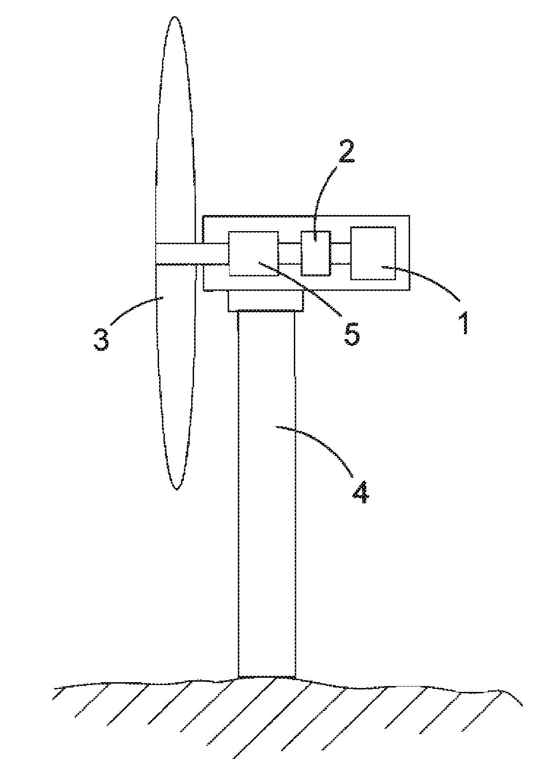
[0044]Currently viable alternative energy sources included wind power, wave power and tidal flow. With the advent of variable speed drive technology in the form of variable speed gearboxes, hydraulic drives and others, it has become feasible to replace variable speed generating equipment with newer technologies utilizing a synchronous machine running at synchronous speed in parallel with the grid transmission or distribution system. An advantage of using synchronous machines running at synchronous speed is that that other power plants also use synchronous generators, and so the behaviour of all of the systems is similar. Other alternative energy designs mainly use inverter technologies. These technologies require complex power electronics, and only partially satisfy the requirements of grid companies in terms of their behaviour in response to variations in grid parameters.

[0045]Sources of alternative energy tend to be located at some distance from centres of population where the ele...


PUM


Abstract

A power generation system is disclosed for supplying power to an electrical grid. The system comprises a synchronous machine and coupling means for coupling the synchronous machine to a prime mover. Control means are provided to control the system such that the system is selectively operable in two modes. In the first mode, the synchronous machine is coupled to the prime mover and acts as a synchronous generator to supply power to the grid. In the second mode the synchronous machine is decoupled from the prime mover and acts as a synchronous condenser. This can allow parameters of the grid, such as power factor and voltage, to be adjusted.

Description

BACKGROUND TO THE INVENTION[0001]The present invention relates to a power generation system for supplying electrical power to a power distribution system, and in particular (although not exclusively) to a power generation system utilising an alternative energy source such as wind power, wave power and tidal flow.[0002]Alternative energy sources are characterised by the fluctuating nature of the energy source. For this reason, power generation systems using alternative energy sources have typically used a variable speed electrical generator coupled to the energy source, together with power electronics at the output of the generator in order to convert the output of the generator into a form suitable for supply to an electrical grid.[0003]With the development of variable speed drive technology, it has now become feasible to use synchronous generators running at synchronous speed in alternative energy power generation systems. Synchronous generators have the advantage that they can be ...

Claims


Application Information

Patent Timeline
IPC IPC(8): H02P9/06
CPCF03D7/0284F03D7/042F03D9/003F05B2220/70642Y02E10/725H02J3/1885Y02E10/723Y02E10/763Y02E40/32F05B2270/337F03D15/10F03D9/255Y02E10/72Y02E10/76Y02E40/30
Inventor TURNER, WILLIAM BRIANBROWN, NEILMEADOWS, RICHARDBIEBIGHAEUSER, ANDREAS
Owner CUMMINS GENERATOR TECH LTD
Learn More