Wind turbine with mixers and ejectors

a wind turbine and mixer technology, applied in the field of wind turbine accessories, can solve the problems of rotor blade breakage, higher power extraction levels, and rotor blades being weakened, so as to improve the sustainable efficiency of wind turbines, reduce noise, and increase operational efficiency

Inactive Publication Date: 2009-04-16
FLODESIGN WIND TURBINE
View PDF52 Cites 39 Cited by
  • Summary
  • Abstract
  • Description
  • Claims
  • Application Information

AI Technical Summary

Benefits of technology

[0016]A method and apparatus are disclosed for improving the sustainable efficiency of wind turbines beyond the Betz limit. Both the method and apparatus use fluid dynamic ejector concepts and advanced flow mixing to increase the operational efficiency, while lowering the noise level, of Applicant's unique wind turbine compared to existing wind turbines.
[0022]First-principles-based theoretical analysis of the preferred method and apparatus indicates that the MEWT can produce three or more times the power of its un-shrouded counterparts for the same frontal area, and increase the productivity of wind farms by a factor of two or more.

Problems solved by technology

In general, for a properly designed rotor, this increased flow speed causes more force on the rotor and subsequently higher levels of power extraction.
Often though, the rotor blades break apart due to the shear and tensile forces involved with higher winds.
Such claims however have not been sustained in practice and existing test results have not confirmed the feasibility of such gains in real wind turbine application.
Gas turbine technology has yet to be applied successfully to axial flow wind turbines.
Both of these effects result in low flow through, turbine velocities.
These low velocities minimize the potential benefits of gas turbine technology such as stator / rotor concepts.
Diffusers require long lengths for good performance, and tend to be very sensitive to oncoming flow variations.
Such long, flow sensitive diffusers are not practical in wind turbine installations.
Short diffusers stall, and just do not work in real applications.
Also, the downstream diffusion needed may not be possible with the turbine energy extraction desired at the accelerated velocities.
These effects have doomed all previous attempts at more efficient wind turbines using gas turbine technology.

Method used


Image

  • Wind turbine with mixers and ejectors
  • Wind turbine with mixers and ejectors
  • Wind turbine with mixers and ejectors

Examples


Embodiment Construction

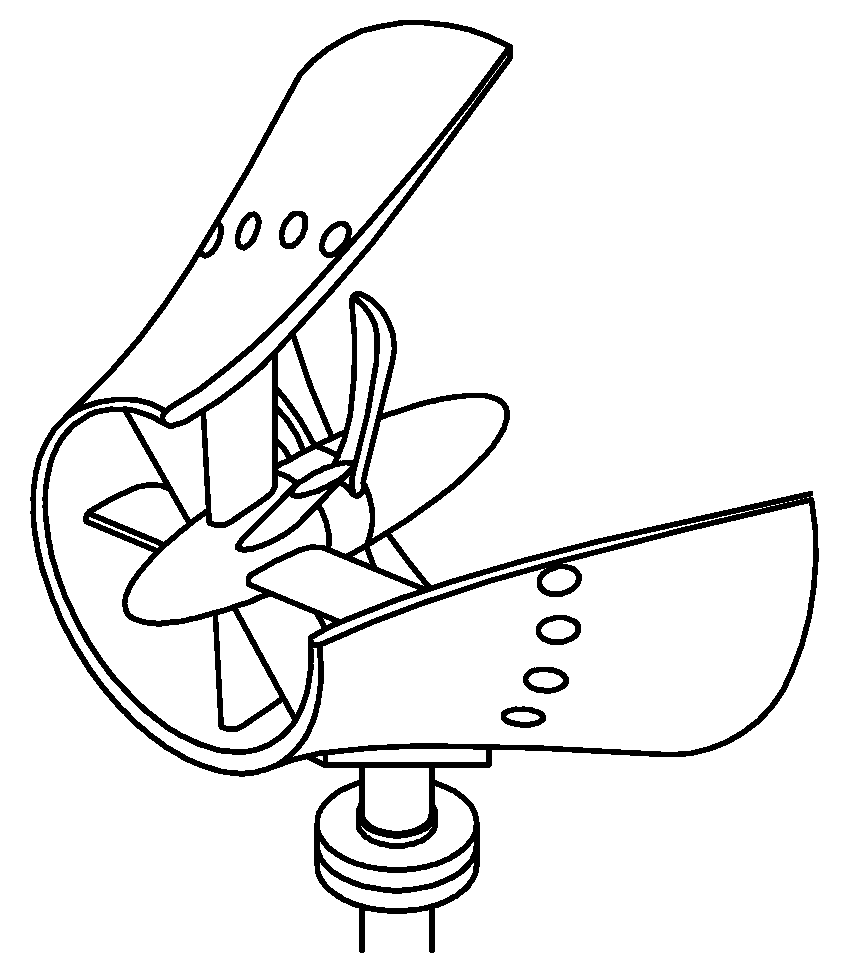
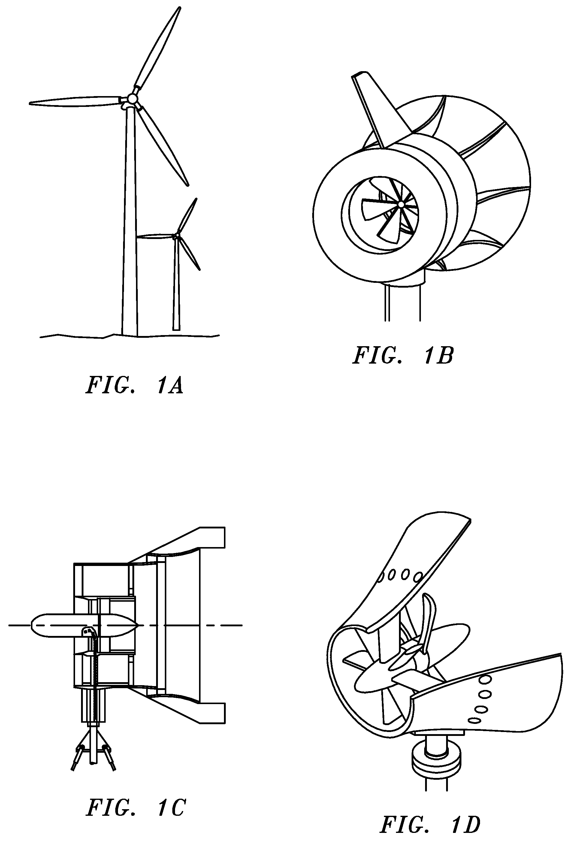
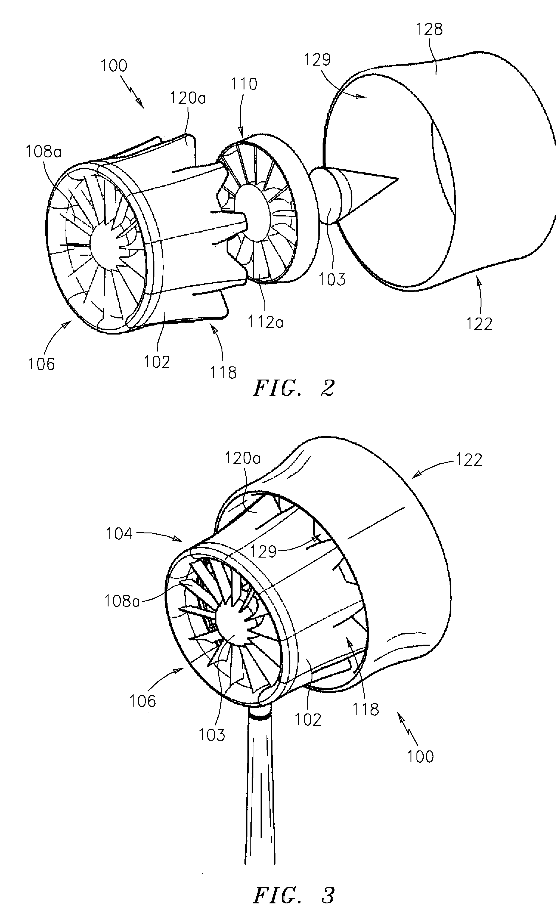
[0051]Referring to the drawings in detail, FIGS. 2-25 show alternate embodiments of Applicants' apparatus, “Wind Turbines with Mixers and Ejectors” (“MEWT”).

[0052]In the preferred “apparatus” embodiment (see FIGS. 2, 3, 4 and 5), the MEWT 100 is an axial flow wind turbine comprising:[0053]a. an aerodynamically contoured turbine shroud 102;[0054]b. an aerodynamically contoured center body 103 within and attached to the turbine shroud 102;[0055]c. a turbine stage 104, surrounding the center body 103, comprising a stator ring 106 of stator vanes (e.g., 108a) and an impeller or rotor 110 having impeller or rotor blades (e.g., 112a) downstream and “in-line” with the stator vanes (i.e., leading edges of the impeller blades are substantially aligned with trailing edges of the stator vanes), in which:[0056]i. the stator vanes (e.g., 108a) are mounted on the center body 103; and[0057]ii. the impeller blades (e.g., 112a) are attached and held together by inner and outer rings or hoops mounted...


PUM


Abstract

A Mixer / Ejector Wind Turbine (“MEWT”) system is disclosed which routinely exceeds the efficiencies of prior wind turbines. In the preferred embodiment, Applicants' MEWT incorporates advanced flow mixing technology, ejector technology, aircraft and propulsion aerodynamics and noise abatement technologies in a unique manner to fluid-dynamically improve the operational effectiveness and efficiency of prior wind turbines, so that its operating efficiency routinely exceeds the Betz limit. Applicants' preferred MEWT embodiment comprises: a turbine shroud with a flared inlet; a ring of stator vanes; a ring of rotating blades (i.e., an impeller) in line with the stator vanes; and a mixer / ejector pump to increase the flow volume through the turbine while rapidly mixing the low energy turbine exit flow with high energy bypass wind flow. Unlike gas turbine mixers and ejectors which also mix with hot core exhaust gases, Applicants' preferred apparatus mixes only two air streams (i.e., wind): a primary air stream which rotates, and transfers energy to, the impeller while passing through the turbine; and a high energy bypass flow or “secondary” air stream which is entrained into the ejector, where the secondary air stream mixes with, and transfers energy to, the primary air stream. The MEWT can produce three or more time the power of its un-shrouded counterparts for the same frontal area, and can increase the productivity of wind farms by a factor of two or more. The same MEWT is safer and quieter providing improved wind turbine options for populated areas.

Description

RELATED APPLICATIONS[0001]This application is a second continuation-in-part application of a co-pending Utility Application, Ser. No. 12 / 054,050, filed Mar. 24, 2008 (hereinafter “Applicants' Parent Application”), which claims priority from Applicants' U.S. Provisional Patent Application, Ser. No. 60 / 919,588, filed Mar. 23, 2007 (hereinafter “Applicants' Provisional Application”). Applicants hereby incorporate the disclosures of Applicants' Parent Application and Applicants' Provisional Application by reference in their entireties.FIELD OF INVENTION[0002]The present invention deals generally with wind turbines. More particularly, it deals with apparatus for wind turbines.BACKGROUND OF INVENTION[0003]Wind turbines usually contain a propeller-like device, termed the “rotor”, which is faced into a moving air stream. As the air hits the rotor, the air produces a force on the rotor in such a manner as to cause the rotor to rotate about its center. The rotor is connected to either an elec...

Claims


Application Information

Patent Timeline
Patent Type & Authority Applications(United States)
IPC IPC(8): F03D1/04F03D11/00
CPCF03D1/04F05B2240/13Y02E10/72F05B2260/96F05B2240/133F03D9/28
Inventor PRESZ, JR., WALTER M.WERLE, MICHAEL J.
Owner FLODESIGN WIND TURBINE
Why Eureka
Try Eureka