Virtual connector based on contactless link

a virtual connector and contactless technology, applied in the direction of radio transmission, electrical equipment, transmission, etc., can solve the problem of low transmission power and other problems

Inactive Publication Date: 2009-04-16
ZACK RAFI
View PDF4 Cites 98 Cited by
  • Summary
  • Abstract
  • Description
  • Claims
  • Application Information

AI Technical Summary

Problems solved by technology

Since the distance is almost zero, the required transmission power is low.

Method used


Image

  • Virtual connector based on contactless link
  • Virtual connector based on contactless link
  • Virtual connector based on contactless link

Examples


embodiment

PREFERRED EMBODIMENT

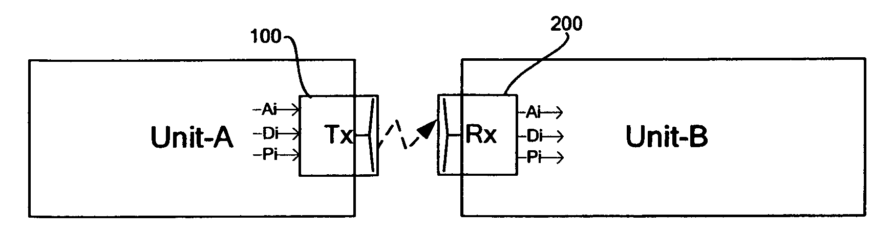
[0030]The innovated contactless system provides an Extremely High Data Rate (EHDR) contactless connector that drives digital and / or analog signals from end to end.

The architecture is optimized for low power and low cost implementation.

The innovated system uses the unlicensed band between 57 GHz-66 GHz. The 60 GHz RF front end is designed to support high efficiency and low power solution, while performance is optimized for the very short ranges. The modulation is based on non-coherent architectures as On / Off Keying (OOK), 4-Levels Amplitude Shift Keying (4-ASK), Differentially Binary Shift Keying (DBPSK) and Differentially Quadrature Shift Keying (DQPSK) that save a simple receiver implementation. FIG. 5 presents the general structure of the contactless transmitter (FIG. 5, 300) and contactless receiver (FIG. 5, 400).

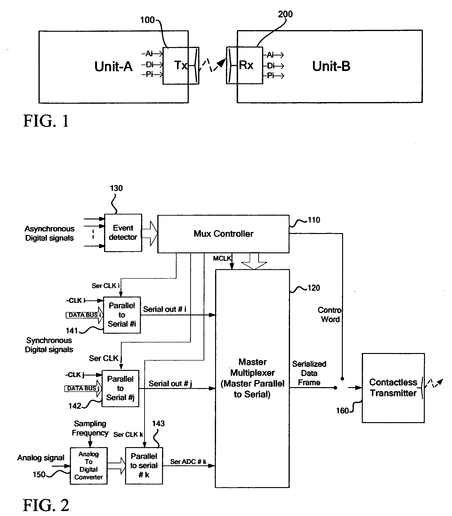
[0031]The transmitter (FIG. 5, 300) of the contactless based virtual connector consists of multiplexer, modulator, RF front-end and antenna. The mult...


PUM


Abstract

The today's mobile handheld and portable devices become slim and thin while need to communicate with other devices and accessories that are attached or at very short range. The interface (contact based physical connector) becomes a real challenge and unreliable to the consumer that needs to attached and detach its device several times a day.
It is an object of the present invention to provide system and method of replacing a contact based physical interface (connector) with very short range wireless (contactless) interface. This technique is called “contactless virtual connector” or CVC. The method of the present invention is based on a transmission of a very low power and wideband RF signal. The new innovating mechanism replaces the traditional physical connector with new radiated signal technique that consumes very low power and may be cost competitive with the today's physical connectors.
The innovated contactless technology may be used for small flexi-cable replacement in the handheld devices as flip or slider based handheld devices. Although the contactess technique is a wireless based solution, yet, the link may be well secured at the Physical layer when the near-field technique is used.

Description

KEYWORDS[0001]Virtual Connector, Contactless, Very short range wireless communication, Extremely High data RateBRIEF DESCRIPTION OF THE DRAWINGS[0002]The present invention will be understood and appreciated more fully from the following detailed description taken in conjunction with the appended drawing in which:[0003]FIG. 1 is a schematic illustration of conceptual contactless virtual connector (CVC) system[0004]FIG. 2 is a schematic illustration of CVC transmitter side[0005]FIG. 3 is a schematic illustration of CVC protocol frame structure[0006]FIG. 4 is a schematic illustration of CVC receiver side[0007]FIG. 5 is a schematic illustration of CVC preferred embodimentBACKGROUND OF THE INVENTION[0008]Virtual Connector is defined as a very short range less then 1 meter, point to point wireless link (contactless link). This link has similar characteristics as a regular connector:[0009]Very Low latency[0010]High reliability link. I.e. very low Bit Error Rate[0011]High quality preservati...

Claims


Application Information

Patent Timeline
Patent Type & Authority Applications(United States)
IPC IPC(8): H04B5/00
CPCH04B1/40
Inventor ZACK, RAFIRAINISH, DORON
Owner ZACK RAFI
Why Eureka
Try Eureka