
Monophasic multi-coil arrays for trancranial magnetic stimulation

a multi-coil array and trancranial magnetic stimulation technology, applied in the field of electromagnets, can solve the problems of increasing the chance, increasing the difficulty of meeting the complexity of the nervous system, and limited current available rtms pulse generator units in their ability,

Inactive Publication Date: 2009-04-16
CERVEL NEUROTECH
View PDF75 Cites 69 Cited by
  • Summary
  • Abstract
  • Description
  • Claims
  • Application Information

AI Technical Summary

Benefits of technology

[0009]A device is described in which a biphasic or polyphasic electrical discharge from a magnetic nerve stimulation or rTMS machine is split into two separate monophasic pulses. These separate pulses are then sent to two separate coils. The method provides for the coordination of pulse polarity, phase, timing, and strength between multiple magnetic stimulation coils. The goal is to optimize the manner in which multiple coils may be used synergistically to control the activity of underlying neural tissue.
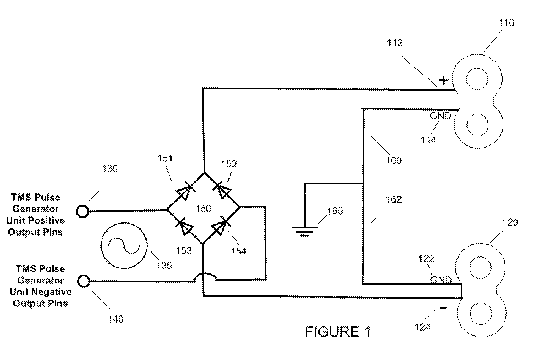
[0010]In one embodiment a biphasic electrical pulse is passed through a high-power bridge rectifier, with the two outputs of which power the positive pole of one double coil and the negative pole of the other double coil, while the remaining pole of each of two double coils are both held to ground. The electrical pulses through each of the coils is thereby monophasic, and the induced magnetic field, is at least substantially monophasic.
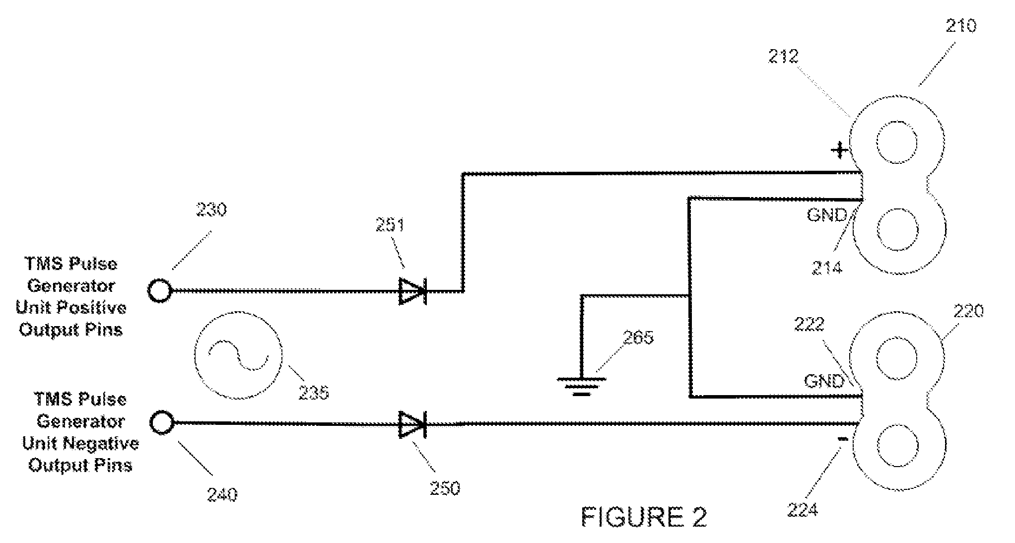
[0011]In an alternative embodiment, the two poles of a biphasic electrical pulse generator are pa...

Problems solved by technology

However, presently available rTMS pulse generator units are limited in their ability to provide the optimal signal to such a coil array.
However, the complexity of the polyphasic waveform, meeting the complexity of the nervous system frequently yields inconsistent results.
In the case of multiple coil stimulation, there is an increased chance that one waveform phase from one coil could diminish or cancel a concurrent phase from another coil
Electrically inefficient, these machines are not capable of sustained, rapid pulse trains.
The prior art does not provide any means for coordinating pulse phase, timing polarity or strength between more than one coil.

Method used


Image

  • Monophasic multi-coil arrays for trancranial magnetic stimulation
  • Monophasic multi-coil arrays for trancranial magnetic stimulation
  • Monophasic multi-coil arrays for trancranial magnetic stimulation

Examples


Embodiment Construction

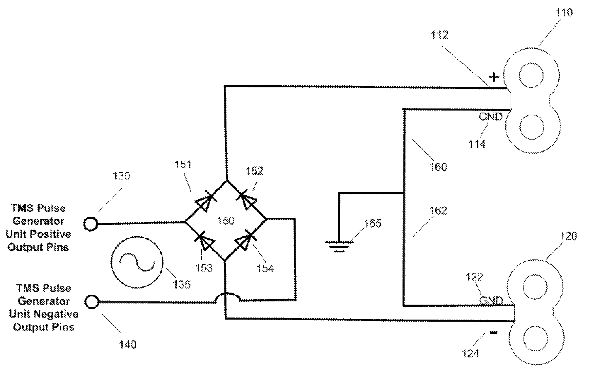
[0023]FIG. 1 shows a circuit diagram of a full-wave rectifier circuit applied to a two-coil array. In this particular embodiment, the two coils in the array, coil 110 and coil 120 are double coils, for example 70 mm double coil manufactured by Magstim Ltd. (Wales, UK). In such a double coil, two separate concentric windings are wrapped in opposite directions with a crossover between the two portions, placed such that the positive and the negative going leads to the two coil portions run electrical current in the same direction where the two portions are adjacent to one another, creating the greatest magnetic field induction under the center. Positive electrical pole 130 and negative electrical pole 140 have a pulsatile polyphasic alternating current 135 between them, and represent the black and red output wire pins on a standard repetitive transcranial magnetic stimulation device. The positive going current from pole 130 and negative going current from pole 140 enter bridge rectifie...


PUM


Abstract

Efficient use of multi-coil arrays for magnetic nerve stimulation depends upon coordinating the coil polarity, the pulse phase and the pulse timing. Monophasic magnetic nerve stimulators produce more precise and predictable results in the stimulation of nerves than biphasic and polyphasic machines, but are less electrically efficient, and consequently limited in terms of pulse train speed. The present invention concerns the coordination of pulse polarity, phase, timing, and strength between multiple magnetic stimulation coils. The goal is to optimize the manner in which multiple coils may be used synergistically to control the activity of underlying neural tissue.

Description

CROSS REFERENCE TO RELATED APPLICATIONS[0001]This application claims priority to U.S. Provisional Patent Application Ser. No. 60 / 954,018, filed on Aug. 5, 2007, titled “MONOPHASIC MULTI-COIL ARRAYS FOR TRANCRANIAL MAGNETIC STIMULATION.”INCORPORATION BY REFERENCE[0002]All publications and patent applications mentioned in this specification are herein incorporated by reference to the same extent as if each individual publication or patent application was specifically and individually indicated to be incorporated by reference.FIELD OF THE INVENTION[0003]The devices and methods described herein relate generally to the use of electromagnets to stimulate the brain treatment of hypertension.BACKGROUND OF THE INVENTION[0004]Concurrent use of more than one magnetic stimulation coil can be used to improve depth of stimulation within a brain, and to help control the location of a deep area of stimulation, as described in Schneider M B et al. 2004 U.S. Ser. No. 10 / 821,807, and Mishelevich et al...

Claims


Application Information

Patent Timeline
IPC IPC(8): A61N2/02
CPCA61N2/02A61N2/004
Inventor SCHNEIDER, M. BRETMISHELEVICH, DAVID J.
Owner CERVEL NEUROTECH
Learn More