Intubation laryngoscope with a double holder

a laryngoscope and double-holder technology, applied in the field of intubation laryngoscopes, can solve the problems of increasing the relatively high cost and complexity and the design complication, so as to achieve the effect of reducing the price of the intubation laryngoscop

Inactive Publication Date: 2009-04-16
M S VISION
View PDF7 Cites 71 Cited by
  • Summary
  • Abstract
  • Description
  • Claims
  • Application Information

AI Technical Summary

Benefits of technology

[0015]The objective of the present invention is substantial decrease in price of laryngoscope due to the capability of using a common single lower holder part for each blade of the blade set.

Problems solved by technology

The disadvantage of the above intubation laryngoscope is its relatively high cost and complexity caused with the necessity to provide each blade of the blade set with its own lower holder part.
Another disadvantage is the need for special ball keeper to prevent the lower holder part from the lateral dislocation in the operation position and from spontaneous falling out from the upper holder part in the inoperative position, resulting in the design complication, rise in price, and weakening the hook strength.
Another disadvantage is the application restrictions of laryngoscope design, specifically, eliminating the capability of the updated blade using without the handle refinement.
Another disadvantage is the load distribution characterized by excessive loading the hook resulting in insufficient hook strength in the version of blade and lower holder part made of plastic.
Another disadvantage is the necessity for arrangement of parts of the illumination system, such as the light guide or the light source, in each blade, leading to increasing the price of the blades and the illumination system.

Method used


Image

  • Intubation laryngoscope with a double holder
  • Intubation laryngoscope with a double holder
  • Intubation laryngoscope with a double holder

Examples


embodiment 400

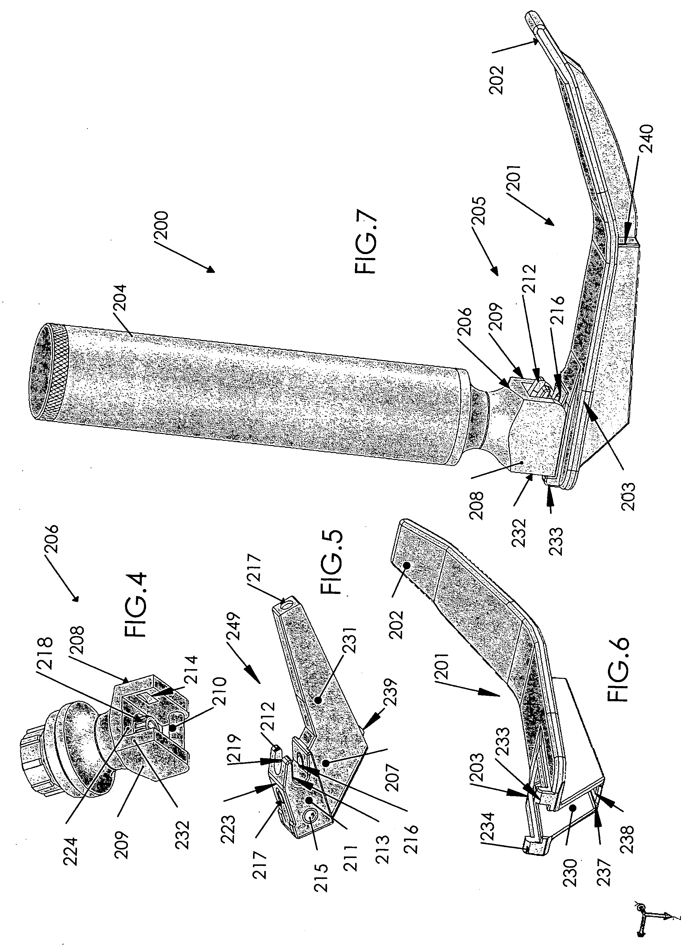
[0094]Version embodiment 400 of the offered intubation laryngoscope, shown in FIGS. 18 to 32, and above laryngoscopes 200, 300 include many elements having identical design and operation and designated by figures with the same two last numerals. Therefore, the following description of version 400 is mainly restricted with its distinctions.

[0095]As distinct from the above laryngoscopes 200 and 300, laryngoscope 400 has the illumination means (FIG. 31) including batteries 421, 422 located within handle 404, and light source 455 in the form of lamp or LED located in a distal end of lower holder part 407. The batteries and light source are connectable through first lead wire 446 and second lead wire 445 located in lower holder part 407. Therewith, first lead wire 446 connects light source 455 immediately with electrical contact 444, which is disposed at upper surface 423 of lower holder part 407 and in the operation position of lower holder part 407 contacting with movable element 418 o...

embodiment 500

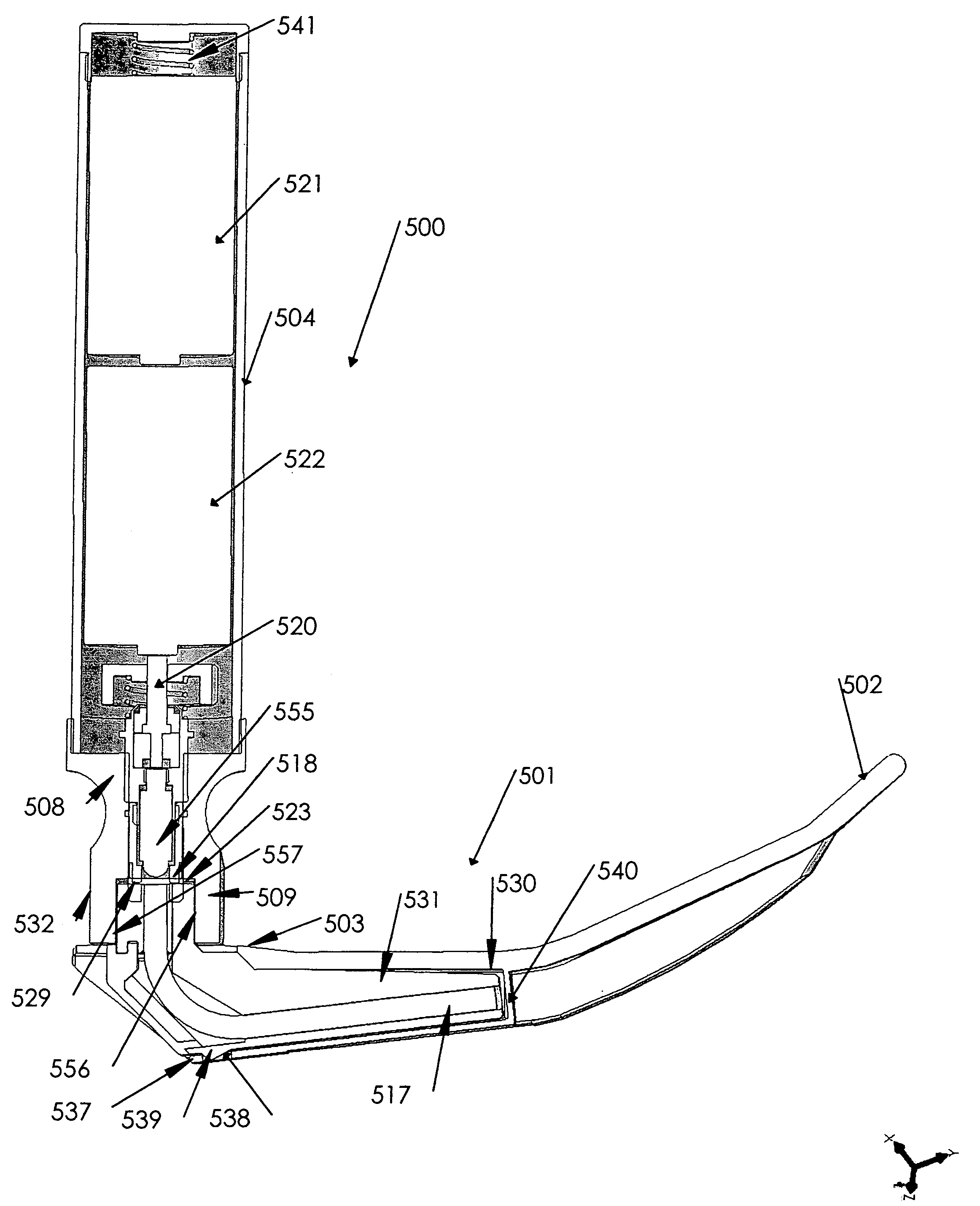
[0100]Version embodiment 500 of the offered intubation laryngoscope, shown in FIGS. 33 to 38, and above laryngoscopes 200, 300, 400 include many elements having identical design and operation and designated by figures with the same two last numerals. Therefore, the description of version 500 is mainly devoted to its distinctions.

[0101]In version embodiment 500 (FIGS. 33 to 38), axle 510 of upper holder part 506 is disposed in parallel to a middle plane passing through a longitudinal axis of handle 504 and a distal direction of extending the detachable blade 50. The middle plane is a secant plane in the cross-sectional view in FIG. 38. Internal surfaces 556, 557 of two lateral walls 508, 509, respectively, are disposed at right angle to the middle plane, while in the prior art and in the above laryngoscopes 200, 300, 400 the axle of upper holder part is disposed at right angle to the middle plane and two lateral walls of the upper holder part have internal surfaces disposed in parall...


PUM


Abstract

Intubation laryngoscope having reusable and disposable blades, an illumination system, and an advantageous fastening appliance for connecting the blades to the laryngoscope handle.

Description

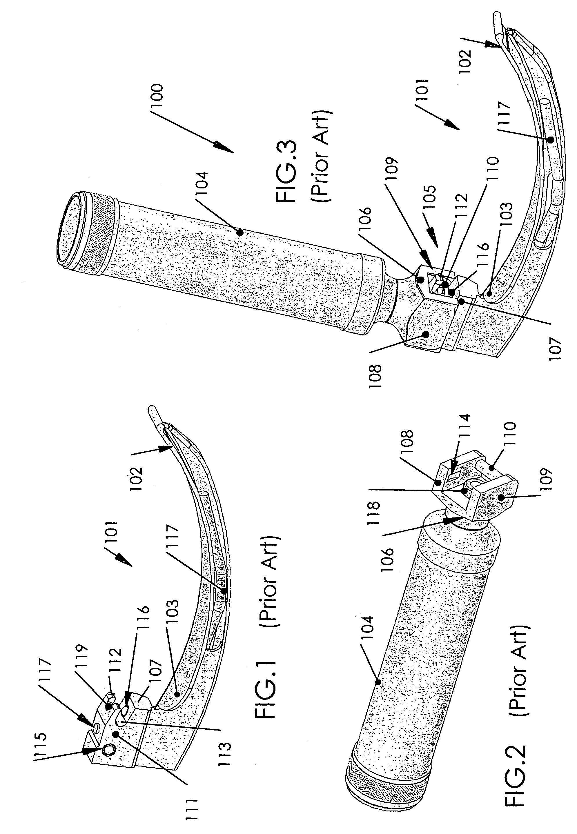
BACKGROUND[0001]1. Field of the Invention[0002]The present invention relates to the intubation laryngoscopes having reusable and disposable blades, an illumination system, and an improved fastening appliance for connecting the blades to the laryngoscope handle.[0003]2. Prior Art[0004]The most widely spread design of intubation laryngoscope 100, for example fabricated by Welch Allyn company (see enclosed FIGS. 1 to 3), comprises a blade set, including four detachable blades of curvilinear Macintosh profile of various sizes designed for operations with children and adults. Each blade 101, made of stainless steel, extends from a lower end of handle 104 in a distal direction and has blade distal end portion 102 designed to expose a tracheal entrance in order to insert an endotracheal tube therein, as well as blade proximal end portion 103 designed for detachable connection with laryngoscope handle 104 through blade holder 105. The latter consists of two parts including upper holder part...

Claims


Application Information

Patent Timeline
Patent Type & Authority Applications(United States)
IPC IPC(8): A61B1/267
CPCA61B1/00103A61B1/00032A61B1/0669A61B1/267
Inventor SHALMAN, MICHEALLUKOV, LEONID
Owner M S VISION
Why Eureka
Try Eureka