Fuel injection control device of internal combustion engine

a control device and internal combustion engine technology, applied in the direction of electric control, ignition automatic control, instruments, etc., can solve the problems of fuel injection in the desired manner, fuel injection in the desired amount may not be able to be achieved, and the pressure in each cylinder continues to fluctuate, so as to reduce the effect of emissions

Inactive Publication Date: 2009-04-16
TOYOTA JIDOSHA KK
View PDF6 Cites 29 Cited by
  • Summary
  • Abstract
  • Description
  • Claims
  • Application Information

AI Technical Summary

Benefits of technology

[0010]It is an object of the invention to provide a fuel injection control device of an internal combustion engine that is...

Problems solved by technology

However, during operation of the internal combustion engine, the pressure in each cylinder continues fluctuating.
Therefore, in the case where fuel is directly injected into the cylinders, a desired manner of injection of fuel may not be able to be achieved due to the effect of fluctuations in the in-cylinder pressure.
Therefore, in the case where fuel is injected to a cylinder at a constant pressure, the amount of fuel injected tends to be larger if fuel is injected during the intake stroke than if fuel is injected during the compression stroke, and thus fuel may not be able to be injected in a desired amount.
Hence, there is a possibility that it may become difficult to control the amount of fuel injection with good accuracy, and the fuel economy performance and the exhaust gas purification performance may reduce.
This restrains excessive increase of the amount of fuel injection in the case where fuel is injected during the intake stroke, during which the in-cylinder pressure becomes low and therefore the amount of fuel injection is likely to become lar...

Method used


Image

  • Fuel injection control device of internal combustion engine
  • Fuel injection control device of internal combustion engine
  • Fuel injection control device of internal combustion engine

Examples


embodiment 1

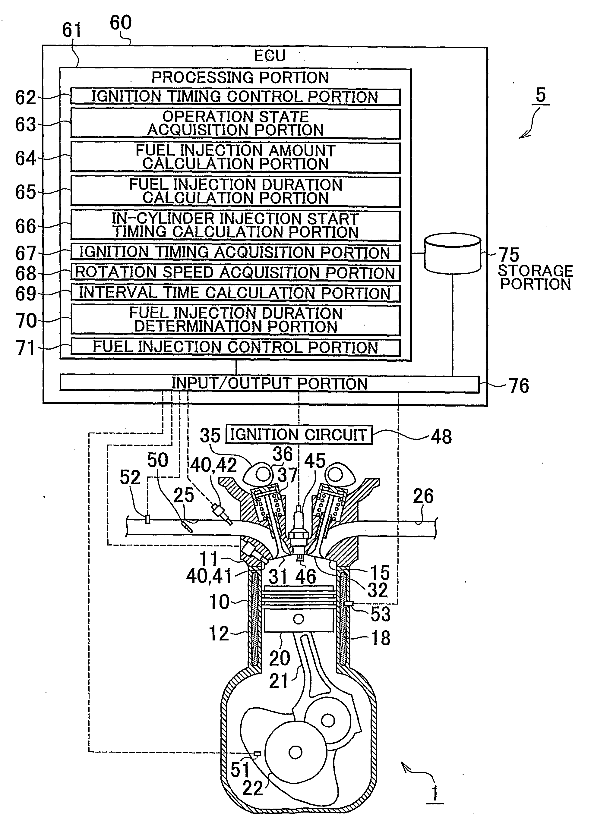
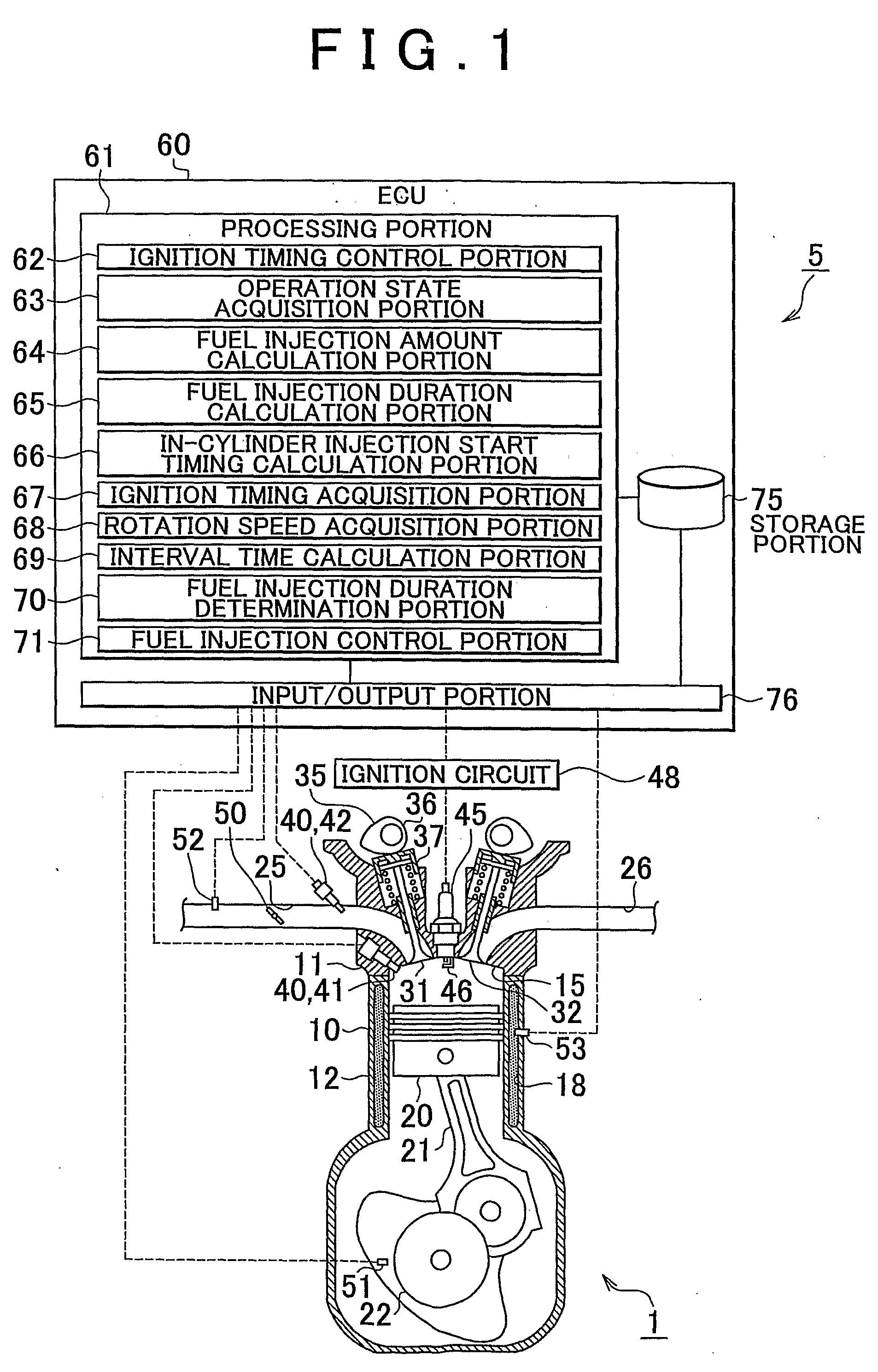
[0034]FIG. 1 is a schematic diagram of an internal combustion engine provided with a fuel injection control device of an internal combustion engine in accordance with Embodiment 1 of the invention. An internal combustion engine 1 shown in FIG. 1 has a plurality of cylinders 10. Each cylinder 10 has a cylinder head 11 and a cylinder block 12 that internally define a combustion chamber 15. Since the cylinders 10 have substantially the same construction, the construction of the internal combustion engine 1 will be described mainly on an arbitrary one of the cylinders 10. Inside the cylinder block 12, a piston 20 is provided for reciprocations within the cylinder 10. A crankshaft 22 that is the cranked shaft is provided in a direction passing through the bottom dead center of the piston 20 that is assumed during operation of the internal combustion engine 1. The piston 20 and the crankshaft 22 disposed as described above are connected by a connecting rod 21. Therefore, the crankshaft 22...

embodiment 2

[0081]A fuel injection control device 80 of an internal combustion engine 1 in accordance with Embodiment 2 has substantially the same construction as the fuel injection control device 5 of the internal combustion engine 1 in accordance with Embodiment 1, but has a feature in that, with regard to the calculation of the fuel injection durations of the injection of fuel from the injectors 40 and the like, the calculation is performed twice, that is, at a stage well earlier than the fuel injection and a stage immediately prior to the in-cylinder fuel injection. Other constructions are substantially the same as those of Embodiment 1, and therefore will not be described below, and will be suffixed with the same reference numerals. FIG. 3 is a schematic diagram of an internal combustion engine provided with a fuel injection control device of an internal combustion engine in accordance with Embodiment 2 of the invention. In a fuel injection control device 80 of an internal combustion engin...

embodiment 3

[0111]A fuel injection control device 90 of an internal combustion engine 1 in accordance with Embodiment 3 has substantially the same construction as the fuel injection control device 5 of the internal combustion engine 1 in accordance with Embodiment 1, but has a feature in that when the in-cylinder injection and the port injection are used in combination at the time of the cold start of the internal combustion engine 1, the combined use thereof is continued until the operation of the internal combustion engine 1 reaches a stable operation. Other constructions are substantially the same as those of Embodiment 1, and therefore will not be described below, and will be suffixed with the same reference numerals. FIG. 5 is a schematic diagram of an internal combustion engine provided with a fuel injection control device of an internal combustion engine in accordance with Embodiment 3 of the invention. In a fuel injection control device 90 of an internal combustion engine 1 shown in FIG...


PUM


Abstract

An internal combustion engine including an in-cylinder injection injector and an intake port-injection injector. An ECU includes a fuel injection duration calculation portion that calculates a requested fuel injection duration and a fuel injection control portion that causes the in-cylinder injection injector to inject fuel during the compression stroke during the cold start of the engine, and that causes fuel to be injected also in a manner other than the fuel injection performed by the in-cylinder injection injector during the compression stroke if the requested fuel injection duration is longer than or equal to an interval time. Therefore, even if the requested fuel injection duration is longer than or equal to the interval time, the emissions can be reduced while a startability during a cold start of the internal combustion engine is secured.

Description

BACKGROUND OF THE INVENTION[0001]1. Field of the Invention[0002]The invention relates to a fuel injection control device of an internal combustion engine. Particularly, this invention relates to a fuel injection control device of an internal combustion engine that is provided in an internal combustion engine that has a fuel injection devices that supply fuel by the injection to intake ports and the injection into cylinders.[0003]2. Description of the Related Art[0004]An internal combustion engine in the related art is equipped with in-cylinder fuel injection means for injecting fuel directly into cylinders of the internal combustion engine. During operation of the internal combustion engine, fuel is supplied by the in-cylinder fuel injection means. However, during operation of the internal combustion engine, the pressure in each cylinder continues fluctuating. Therefore, in the case where fuel is directly injected into the cylinders, a desired manner of injection of fuel may not be ...

Claims


Application Information

Patent Timeline
IPC IPC(8): F02D41/30F02D41/02F02D41/06F02D41/34
CPCF02D41/064F02D41/3094Y02T10/44F02P5/045F02D41/345Y02T10/40
Inventor DEMURA, TAKAYUKI
Owner TOYOTA JIDOSHA KK
Why Eureka
Try Eureka