Powered air cleaning system and air cleaning method

a technology of air cleaning system and air cleaning method, which is applied in the direction of liquid degasification, auxillary pretreatment, separation processes, etc., can solve the problems of increasing the restriction of airflow through the filter, increasing the cost of operation, and reducing so as to reduce the operating performance of an associated device and increase the cost of operation.

Active Publication Date: 2009-04-23
SY KLONE
View PDF27 Cites 46 Cited by
  • Summary
  • Abstract
  • Description
  • Claims
  • Application Information

AI Technical Summary

Benefits of technology

[0002]Air intakes that centrifugally separate heavier-than-air particles from the air to be used in internal combustion engines, ventilation systems, and other apparatus that draw in air laden with debris, are known. The use of in-line filters in air delivery systems to clean the air is also, per se, known. However, air filters are subject to plugging by debris from the air passing

Problems solved by technology

However, air filters are subject to plugging by debris from the air passing through the filter, which eventually increases the restriction to airflow through the filter and decreases the operating performance of an associated device, such as an electronically controlled internal combustion engine being supplied with air through the filter.
Frequent filter replacement and shorter service intervals may also be required, which increases the cost of operation.
When the airflow requirement of a device is reduced to less than the maximum airflow requirement, there is an inefficiency in that the air cleani

Method used


Image

  • Powered air cleaning system and air cleaning method
  • Powered air cleaning system and air cleaning method
  • Powered air cleaning system and air cleaning method

Examples


Embodiment Construction

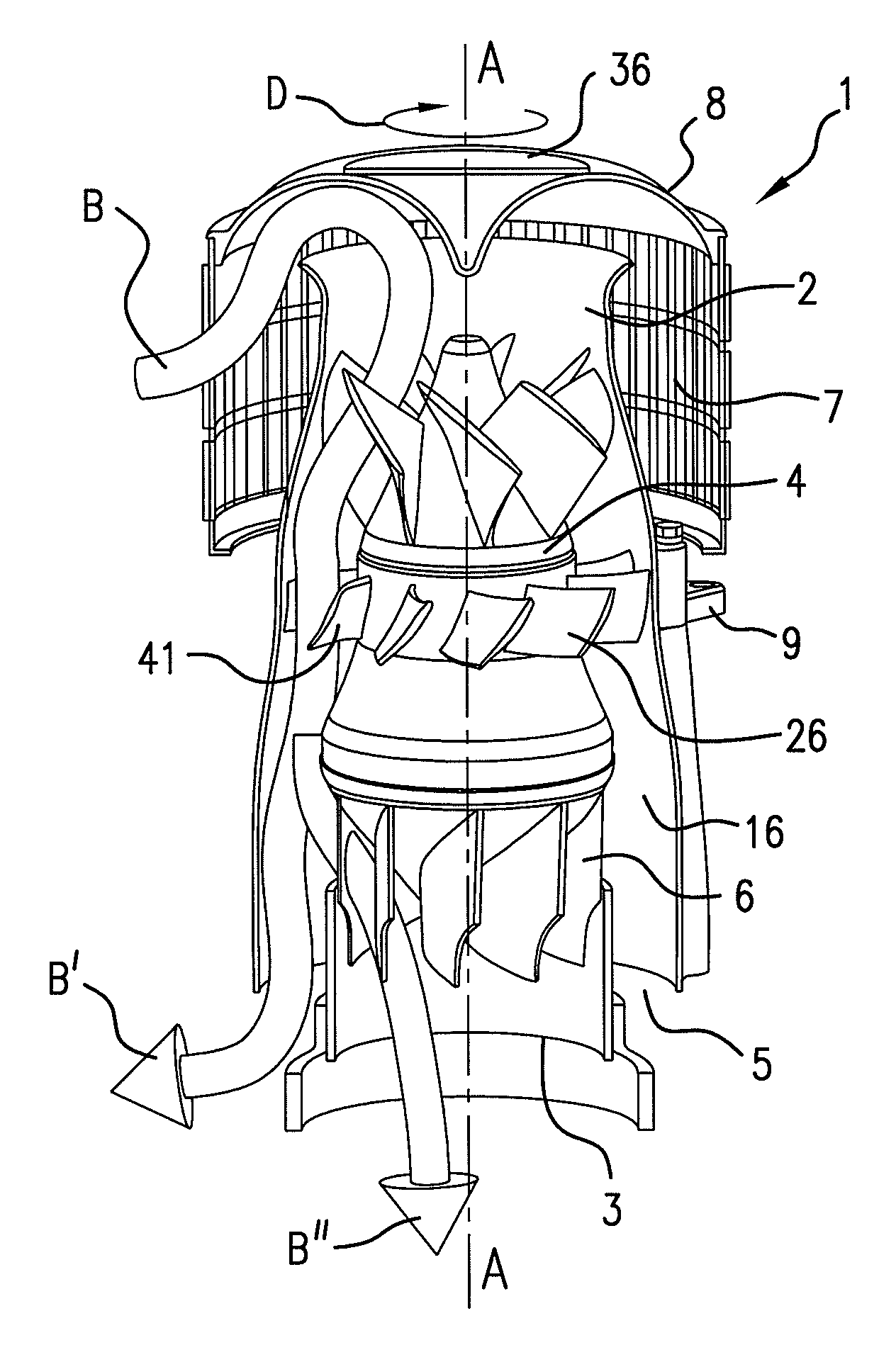
[0040]Referring now to the drawings, the powered air cleaning system 1 comprises a flow path shown by the arrows B, B′ and B″ in FIG. 1 extending through the system from an inlet 2 to an outlet 3. A motor-driven, turbine-type fan 4 is located along the flow path to draw particulate debris laden air into the inlet and rotate it about a longitudinal axis A-A of the system to form a rotating flow that stratifies the debris laden air with the heaviest particles in the outermost orbits of the rotating flow. An ejector port 5 is provided for ejecting particulate debris laden air, B′, from the stratified rotating flow in the system. A plurality of stationary de-swirl blades 6, concavely curved radially in a direction opposite the direction of the rotating flow in the system, are located within the rotating flow centered in the outlet 3 for aerodynamically redirecting clean air from the innermost orbits of the stratified rotating flow toward and through the outlet; see arrow B″. This result...


PUM

PropertyMeasurementUnit
Angular velocityaaaaaaaaaa
Pressureaaaaaaaaaa
Diameteraaaaaaaaaa

Abstract

A powered air cleaning system has a flow path extending through the system from an inlet to an outlet. A motor-driven fan is located along the flow path to draw particulate debris laden air into the inlet and rotate it about an axis to form a rotating flow that stratifies the debris laden air with the heaviest particles in the outermost orbits of the rotating flow. An ejector port ejects particulate debris laden air from the stratified rotating flow in the system. At least one de-swirl component located within the rotating flow aerodynamically redirects clean air from the innermost orbits of the stratified rotating flow toward the outlet to provide a positive airflow pressure out of the outlet. The system has a variable speed fan motor and an integrated controller for adjusting the speed of the motor and thereby the flow rate of clean air through the outlet of the system. The controller receives a signal that is a function of airflow requirements of a device supplied with clean air by the system. The system can be mounted above or below a hood housing an engine to be supplied with clean air.

Description

TECHNICAL FIELD[0001]The present invention is directed to an improved powered, atmospheric ejective, air cleaning system and air cleaning method for efficiently removing debris from debris laden air to supply clean air to a device with which the system is used based on the airflow requirements of the device. For example, the invention is useful in connection with total airflow applications such as ventilation systems, as a fixed airflow provider for heat exchangers and heating and air conditioning systems, and with devices having a variable airflow demand, particularly internal combustion engines which exert a variable vacuum on their air intake to be supplied with clean air.BACKGROUND AND SUMMARY[0002]Air intakes that centrifugally separate heavier-than-air particles from the air to be used in internal combustion engines, ventilation systems, and other apparatus that draw in air laden with debris, are known. The use of in-line filters in air delivery systems to clean the air is als...

Claims


Application Information

Patent Timeline
IPC IPC(8): B01D45/12
CPCB01D45/16
Inventor MOREDOCK, JAMES G.
Owner SY KLONE
Why Eureka
Try Eureka