Method for the separation of gases

a gas separation and gas technology, applied in the field of improved gas separation methods, can solve the problems of significant energy and maintenance costs to the process operating costs, inability to achieve practical solutions for algae, and low cosub>2 /sub>permeability of membranes, so as to reduce the area of membranes, improve the permeability of membranes, and reduce the cost

Inactive Publication Date: 2012-03-08
ECO TECHNOL
View PDF6 Cites 28 Cited by
  • Summary
  • Abstract
  • Description
  • Claims
  • Application Information

AI Technical Summary

Benefits of technology

[0186]This arrangement provides the opportunity to use a lower cost membrane material in the first stage membrane process 30, compared to the membrane material used in the purification step 50. An additional benefit of using a higher permeability membrane in the first membrane system 30 is to reduce the membrane area required to capture the CO2 and therefore helps reduce the footprint and capital cost of the plant. This is an important aspect of the process since the first membrane stage will treat the largest volume of flue gas.
[0187]One significant advantage of the present invention is the use of a first membrane separation system 30 utilising high permeability / low selectivity membranes having a flat sheet or spiral wound construction, which is a design well suited to dealing with the dust and particulates in the gas 27. Substantially all of the dust and particulates are rejected, as well as a significant portion of the N2, into stream 32, while simultaneously concentrating the CO2 into the pre-concentrated gas stream 34.
[0188]It is envisaged that in some circumstances tubular, hollow fibre, or ceramic construction membranes can also used in the first membrane separation system 30, depending on the gas composition in stream 27, for example, dust loading may be low or absent as would be the case for exhaust gas from a gas fired power station, or the gas volume to be treated is small, or due to downstream process requirements.
[0189]Hollow fibre membranes are preferred for the purification step 50, as they are more prone to fouling by dust. Therefore, they are better suited for use once the pre-concentrated gas stream 34 has been “cleaned” and dust particles removed. It is understood that hollow fibre membranes may have a higher flow resistance compared to other membrane constructions such as spiral wound membranes, so operating costs would be higher. That is, the system would need more energy to pump gas through the membranes. However, given the volume of the pre-concentrated gas stream 34 has been significantly reduced, the net effect on operating expenditure is reduced. For the same reason, i.e. the reduced volume of the gas stream 34, capital costs for the second membrane stage 50 can also be minimised.
[0190]It is envisaged that overall process could comprise either the same membrane materials in each stage, or different membrane materials in each stage.
[0191]The process ideally uses different membrane constructions in combination, for example the first membrane separation system 30 may use a spiral wound membrane construction, and the purification step 50, a hollow fibre membrane construction, or it could employ a spiral wound construction followed by flat sheet or tubular, etc. Alternatively, the same membrane constructions could be used for both the first membrane separation system 30 and the purification step 50.

Problems solved by technology

However, algae is not currently a practical solution because of the very large area required to grow the algae.
The amine absorption process requires a gas-to-liquid phase change in the gas mixture that is to be separated which adds a significant energy and maintenance costs to the process operating costs; membrane gas separation does not require a phase change and so less energy is required;b) Smaller capital costs.
However, these membranes do not have very high CO2 permeability, whereas other membranes, for example PTMSP have very high CO2 permeability, but are not robust enough to handle prolonged exposure to a post combustion flue gas.
As outlined above, a substantial problem with CO2 capture processes is the sheer volume of gas that needs to be handled.
Clearly the large capital expenditure (CAPEX) required to achieve this is a significant deterrent to organisations for incorporating CO2 capture processes.
Whilst the oxyfuel combustion process improves the CO2 content of the flue gas stream, the cost of producing large volumes of concentrated oxygen and incorporating such a process into an existing plant is significant.
Furthermore, it may not be compatible with existing infrastructure because burners in existing plants may not be able to operate efficiently under such high oxygen gas conditions.
Alternatively, the burners themselves may be damaged.
Another complication associated with wet FGD systems is that the flue gas exiting the absorber is cooled to below 100° C., eg typically below 60° C. and is saturated with water as well as still containing some SO2.
This results in the formation of acidic condensate (SO3 / H2SO4) which leads to increased chemical corrosion to downstream equipment.
However reheating is still required for stack gas buoyancy.
Both alternatives are expensive and must be considered on a by-site basis.
After treatment with either limestone or lime slurry the flue gases will contain entrained particles of CaSO3 / CaSO4 which are highly scaling, making it problematic to feed the gas into any further downstream treatment processes such as a membrane system for recovering CO2.
However sodium hydroxide is much more expensive than lime or limestone and is seldom used for scrubbing the large flue gas volumes produced from a power station.
In addition any particulates remaining in the scrubbed flue gas will build-up within the scrubbing solution and eventually will have to be removed from the system, resulting in a toxic solid waste which must be properly handled and disposed.
The presence of impurities including dust and particulates can foul or block a membrane capture system.
Even with a gas particle filter some dust particles still remain in the flue gas and these can deposit and build-up over time on the membrane surface and foul the membrane.
If the membrane system is installed downstream of an FGD there is the added potential for gypsum particulates to be present in the scrubbed gas which can foul the membranes and make them difficult to clean.

Method used


Image

  • Method for the separation of gases
  • Method for the separation of gases
  • Method for the separation of gases

Examples


example 1

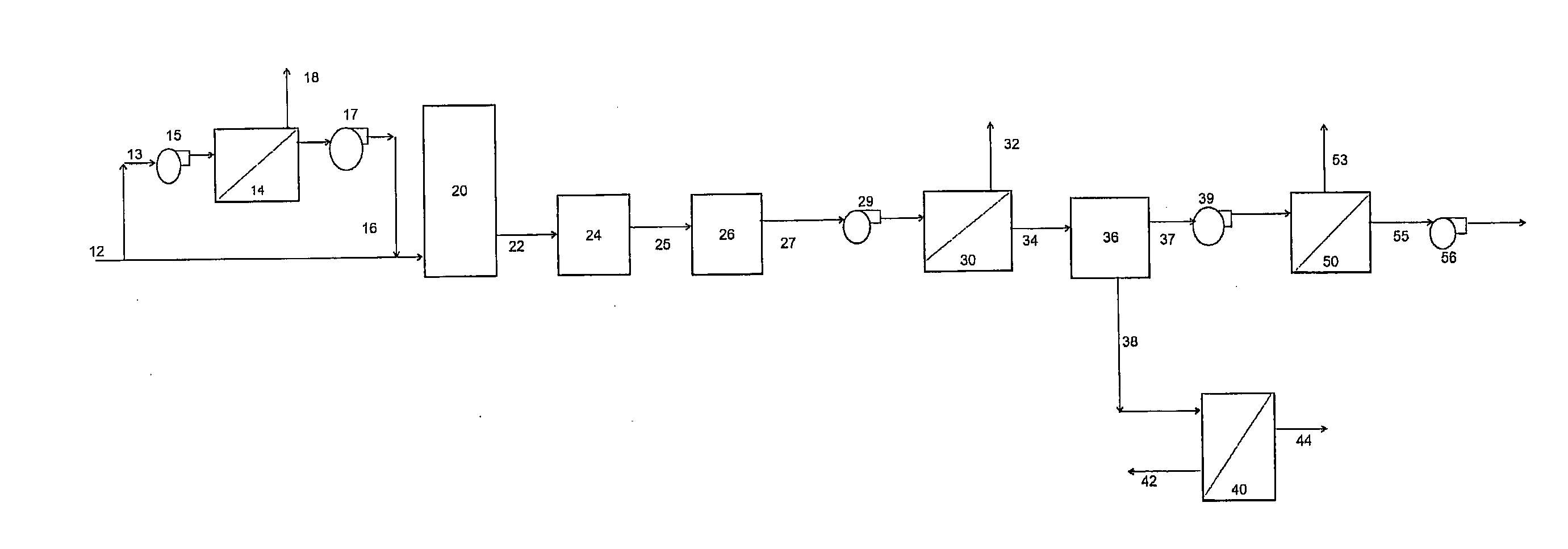
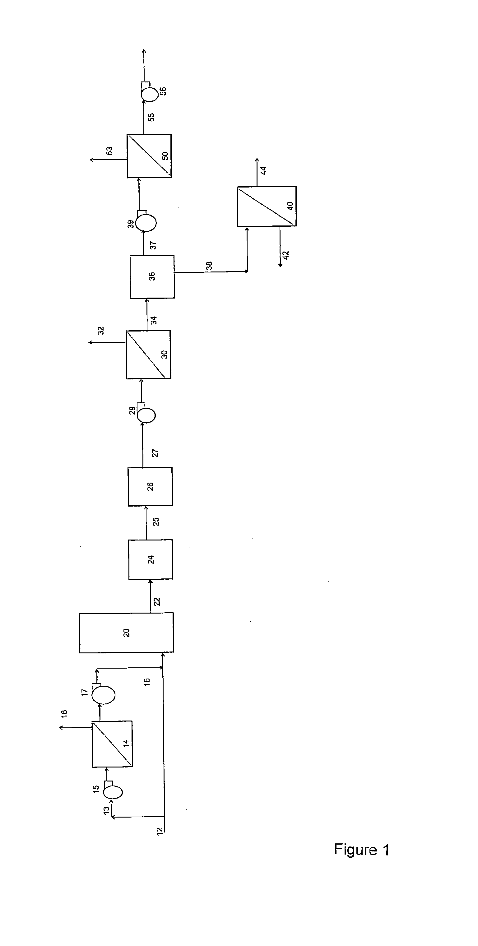
[0221]Example 1 demonstrates the application of a 2 stage membrane separation process as shown in FIG. 1. However, as the process was operated at room temperature, no gas cooling step was required. The feed gas stream, comprised a bottled gas mixture of 85% (v / v) N2, 10% (v / v) CO2, and 5% (v / v) O2 and was passed through a first membrane separation system, comprising one spiral wound polydimethyl siloxane membrane. The permeate stream, was collected using a vacuum pump, and pumped through a membrane purification system, comprising one spiral wound polydimethyl siloxane membrane. The final permeate (purified CO2 stream), was collected using a second vacuum pump. Both membranes had a CO2 permeability of approximately 4000 Barrer and a CO2 / N2 selectivity of approximately 11. The 2 stage membrane separation step achieved approximately 86% CO2 (v / v) purity, with a total CO2 recovery of approximately 83%.

[0222]The results of this test are provided in Table 1.

TABLE 1Stream No2734325553Strea...

example 2

[0223]Example 2 demonstrates the application of a 2 stage membrane separation process as shown in FIG. 1. However, as the process was operated at room temperature, no gas cooling step was required. The feed gas, stream, comprised a bottled gas mixture of 85% (v / v) N2, 10% (v / v) CO2, and 5% (v / v) O2 and was passed through a first membrane separation system, comprising one spiral wound polydimethyl siloxane membrane. The permeate, stream, was collected using a vacuum pump, and pumped through a membrane purification system comprising one hollow fibre polyimide membrane. The final permeate (purified CO2 stream), was collected using a second vacuum pump. The polydimethyl siloxane membrane had a CO2 permeability of approximately 4000 Barrer and a CO2 / N2 selectivity of approximately 11, while the polyimide membrane had a CO2 permeability of approximately 500 Barrer and a CO2 / N2 selectivity of approximately 23. The 2 stage membrane separation step achieved approximately 93% CO2 (v / v) purity...

example 3

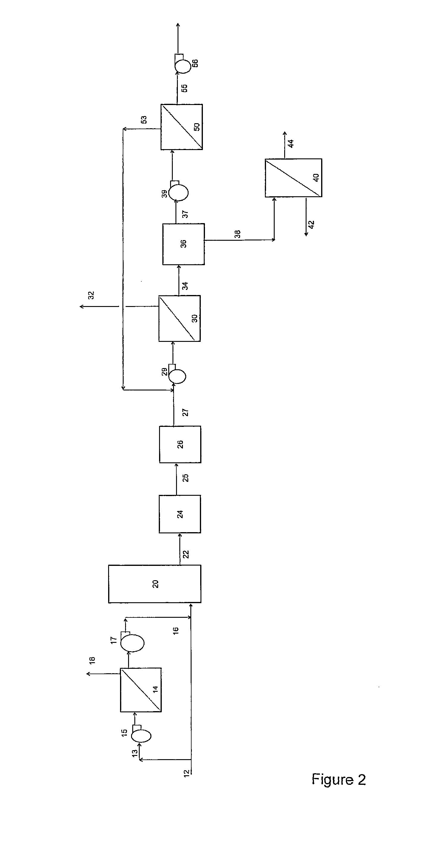
[0226]Example 3 demonstrates the application of a 2 stage membrane separation process as shown in FIG. 2, in which a slip stream of exhaust gas, from a natural gas fired combustion process was pumped through a first membrane separation system, comprising one spiral wound polydimethyl siloxane membrane. The permeate, was cooled in a gas cooler, upstream of a vacuum pump, and then pumped through a membrane purification system comprising one spiral wound polydimethyl siloxane membrane. The final permeate, was collected using a second vacuum pump. The reject gas from the membrane purification system, was recycled to the feed of the first membrane separation system.

[0227]Both membranes had a CO2 permeability of approximately 4000 Barrer and a CO2 / N2 selectivity of approximately 11. The 2 stage membrane separation step achieved approximately 92% CO2 (v / v) purity in the final permeate stream, with a total CO2 recovery over 90%.

[0228]The results of this test are provided in Table 3.

[0229]Th...


PUM


Abstract

A method (10) for the separation of gases involving the method steps of: i) passing an exhaust gas stream (27) containing CO2 through a first membrane separation system (30) to produce a pre-concentrated gas stream (34) containing at least carbon dioxide; and a reject stream; and ii) directing the pre-concentrated gas stream to at least one purification step (50) to produce a purified CO2 stream (55); wherein, sulphur-containing gases (SOx) are also substantially separated from the exhaust gas (27) by the first membrane separation step (30) into the pre-concentrated gas stream (34), and the purified CO2 stream (55) is substantially free of nitrogen gas.

Description

FIELD OF THE INVENTION[0001]The present invention relates to an improved method for the separation of gases. In particular, the method of the present invention involves capture of carbon dioxide and other desirable gases and removal of impurities therefrom, using membrane separationBACKGROUND ART[0002]Methods for the recovery of carbon dioxide (CO2) from combustion processes have attracted more attention in recent times due to global warming and the potential for carbon trading. Whilst CO2 emissions can be reduced by modifying industrial plants and converting to natural gas (rather than the combustion of coal), many organisations understand that CO2 capture provides better control over how much CO2 is released to the atmosphere, and potentially greater impact on both capital and operating costs. A number of technologies are known for capturing CO2; these include cryogenic distillation processes, adsorption and absorption processes and membrane separation.[0003]To date there have bee...

Claims


Application Information

Patent Timeline
Patent Type & Authority Applications(United States)
IPC IPC(8): B01D53/22F23J15/02B01D53/56B01D53/62B01D53/48
CPCB01D53/226B01D2257/302Y02C10/10B01D2257/504B01D2257/80B01D2257/404Y02E20/32Y02C20/40
Inventor LIEN, LARRY ALLENPICARO, TONY
Owner ECO TECHNOL
Why Eureka
Try Eureka