Photovoltaic system

a photovoltaic system and photovoltaic technology, applied in the field of photovoltaic systems, can solve the problems of high affinity, premature permanent power drop, and danger of electric shock for people standing on the ground who touch lines or conductor parts, and achieve the effect of preventing damage in the edge regions of solar modules

Active Publication Date: 2009-04-23
PADCON
View PDF6 Cites 135 Cited by
  • Summary
  • Abstract
  • Description
  • Claims
  • Application Information

AI Technical Summary

Benefits of technology

[0016]The disclosed system according to the invention essentially eliminates “cathode discharges” and thereby prevent damage in the edge regions of the solar modules.
[0018]With this measure, the negative potential is shifted up, preferably to a positive value with respect to ground potential, which reduces or completely eliminates “cathode discharges”, i.e., flow of electron into the various modules.

Problems solved by technology

The basic disadvantage of the circuit of FIG. 1 is its high affinity to “attract” lightning due to the connection of the negative potential to ground.
There is a danger of an electric shock for a person standing on the ground who touches lines or conductor parts at, for example, the maximum line voltage U0.
This photovoltaic system 1 reduces the risk for lightning strikes and eliminates the danger of an electric shock for bystanders, but has another disadvantage.
Conversely, a discharge from cathodes causes damage to the photovoltaic modules over an extended period of time, damaging (eroding) the edge region of the TCO layer of the photovoltaic modules 3 and causing a premature permanent power drop.
As already mentioned, “electron absorption” can damage the modules 3b during their service life.
In case of an electrical fault, conventional equipment with potentially exposed electrical high-voltage components puts service personnel at risk.
This may take several weeks in large high-power photovoltaic systems and is therefore not practical.
In addition, it is also not possible to detect when one or more parallel-connected strings 5 of photovoltaic modules 3 are disconnected, either because these modules 3 became defective or due to theft.

Method used


Image

  • Photovoltaic system
  • Photovoltaic system
  • Photovoltaic system

Examples


Embodiment Construction

[0028]Throughout all the figures, same or corresponding elements may generally be indicated by same reference numerals. These depicted embodiments are to be understood as illustrative of the invention and not as limiting in any way. It should also be understood that the figures are not necessarily to scale and that the embodiments are sometimes illustrated by graphic symbols, phantom lines, diagrammatic representations and fragmentary views. In certain instances, details which are not necessary for an understanding of the present invention or which render other details difficult to perceive may have been omitted.

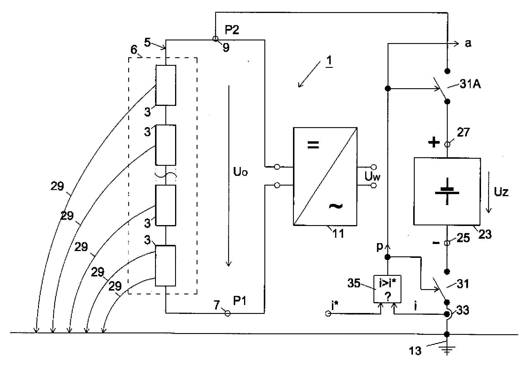
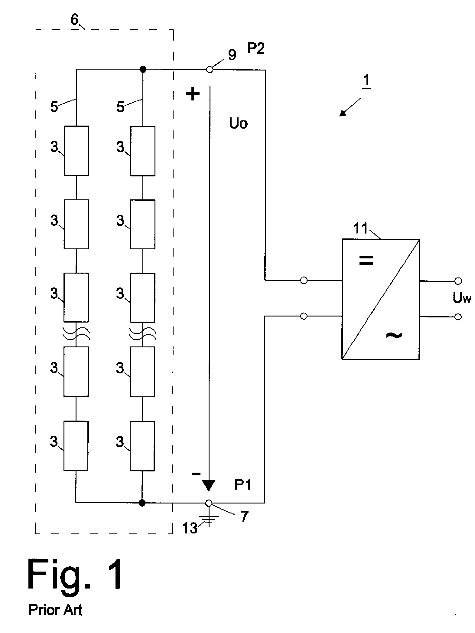
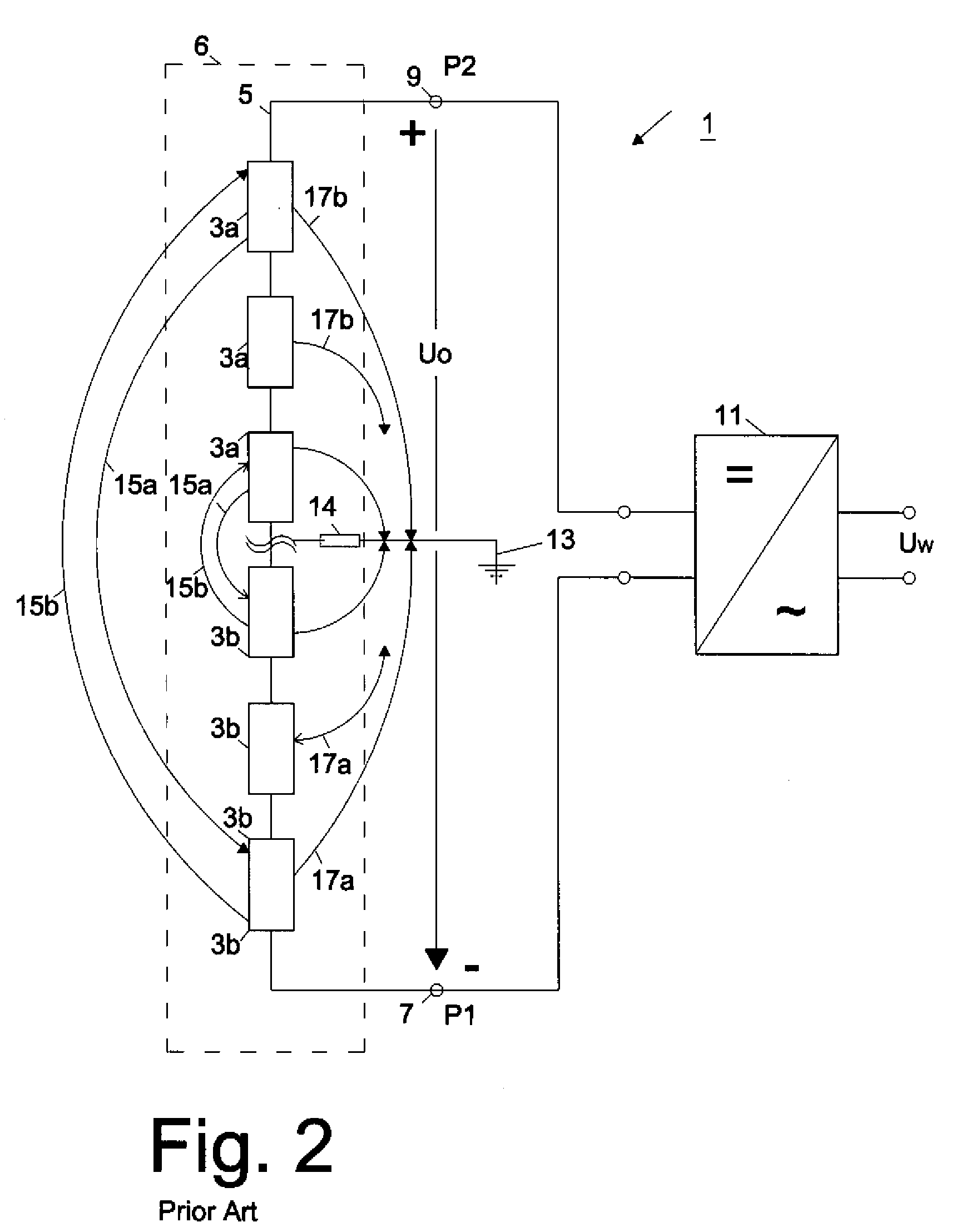
[0029]Turning now to the drawing, and in particular to FIGS. 1 and 2, there are shown schematic diagrams of a conventional grounded and a conventional potential-free photovoltaic system 1, respectively, which have already been described above. The photovoltaic system 1 in FIG. 1 is grounded, i.e. the negative potential P1 at the first string terminal 7 is connected to ground...


PUM


Abstract

The photovoltaic system includes a plurality of photovoltaic modules which are connected to form a string or several strings connected in parallel, thereby forming a photovoltaic generator having a positive terminal and negative terminal. A DC constant voltage source connected to the photovoltaic generator to raise the potential of the positive terminal relative to ground potential. This reduces the flow of electrons out of the TCO layer of the modules, thereby reducing or completely eliminating cathode discharges which damage the modules.

Description

CROSS-REFERENCES TO RELATED APPLICATIONS[0001]This application claims the priority of German Patent Application, Serial No. 10 2007 050 554.1, filed Oct. 23, 2007, pursuant to 35 U.S.C. 119(a)-(d), the content of which is incorporated herein by reference in its entirety as if fully set forth herein.BACKGROUND OF THE INVENTION[0002]The present invention relates to a photovoltaic system and more particularly to a photovoltaic system with a plurality of electrically connected photovoltaic modules.[0003]Photovoltaic systems are generally known. These systems typically include a number of photovoltaic modules connected in series to form a so-called string. Each photovoltaic module in turn includes about 100 photovoltaic cells, which are also electrically connected in series. A single photovoltaic cell generates a voltage of about 0.5 V when illuminated by sunlight. As a result, each string has under load a voltage across the string of about 500 V depending on the specific application of ...

Claims


Application Information

Patent Timeline
Patent Type & Authority Applications(United States)
IPC IPC(8): H01L27/142
CPCH01L31/02021Y10S136/293Y02E10/50
Inventor BECK, BERNHARDMULLER, TIM
Owner PADCON
Why Eureka
Try Eureka