
Hybrid vehicle and controlling method thereof

Active Publication Date: 2009-04-23
TOYOTA JIDOSHA KK
View PDF13 Cites 81 Cited by
  • Summary
  • Abstract
  • Description
  • Claims
  • Application Information

AI Technical Summary

Benefits of technology

[0008]Accordingly, the present invention has been made to solve such a problem. An object of the present invention is to provide a hybrid vehicle in which a battery can be charged from a source external to the vehicle, and with which reduction in the electricity costs can be achieved.

Problems solved by technology

In the hybrid vehicle, when the vehicle travels for a long time without being charged from an external source, the output of the electric motor is limited, and necessarily, when traveling is continued using fuel by the internal combustion engine, the output of the electric motor is limited.
However, Japanese Patent Laying-Open No. 8-154307 does not particularly consider about the electricity costs of charging from an external source.
It is a critical problem for the hybrid vehicle provided with the externally charging function to reduce the electricity costs.

Method used


Image

  • Hybrid vehicle and controlling method thereof
  • Hybrid vehicle and controlling method thereof
  • Hybrid vehicle and controlling method thereof

Examples


first embodiment

[0042

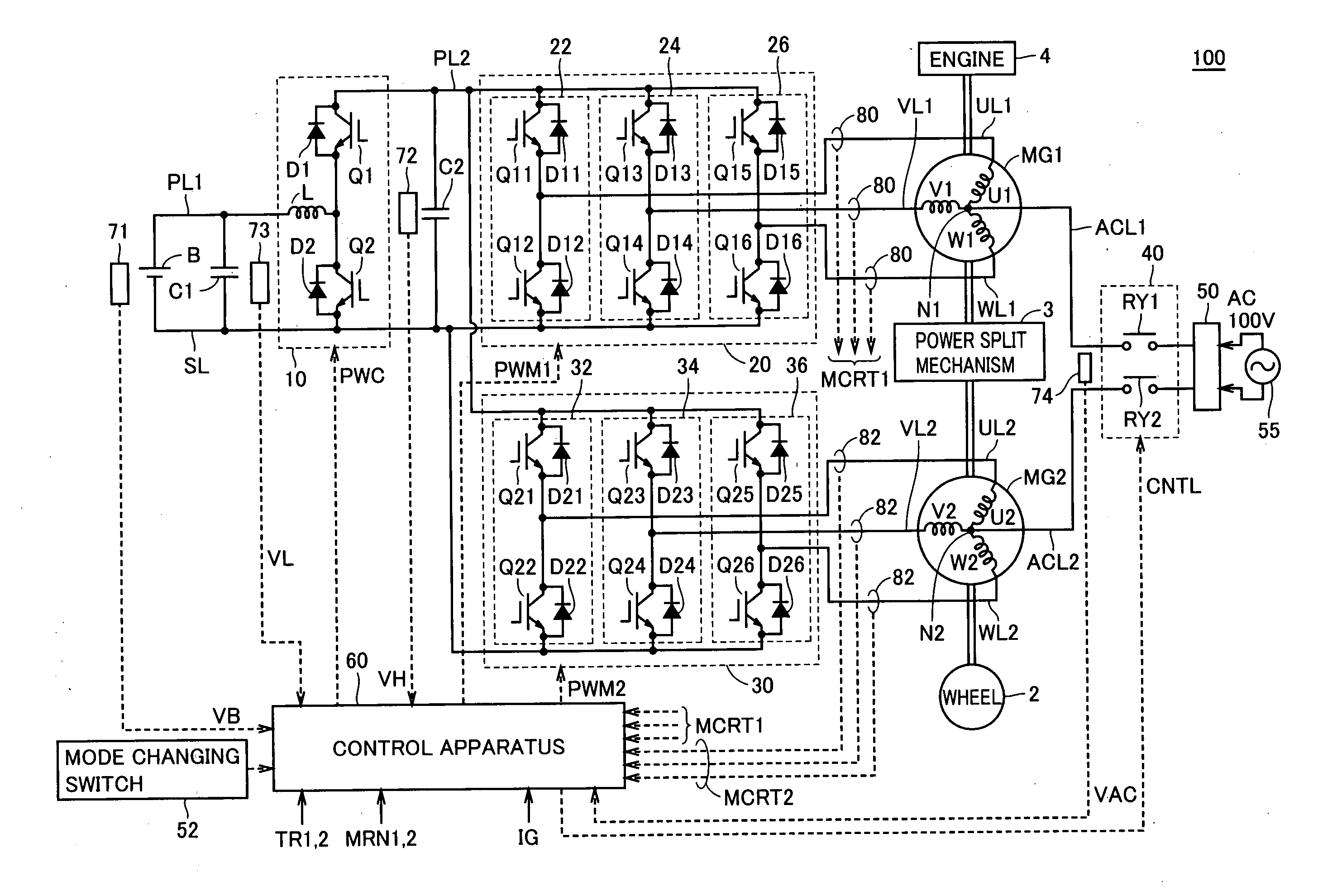
[0043]FIG. 1 is an overall block diagram of a hybrid vehicle according to a first embodiment of the present invention. Referring to FIG. 1, a hybrid vehicle 100 includes battery B, a boost converter 10, inverters 20, 30, power supply lines PL1, PL2, an earth line SL, U-phase lines UL1, UL2, V-phase lines VL1, VL2, W-phase lines WL1, WL2, motor-generators MG1, MG2, an engine 4, a power split mechanism 3, and wheels 2.

[0044]Power split mechanism 3 is a mechanism linked to engine 4 and motor-generators MG1, MG2 for distributing motive power among them. For example, as power split mechanism 3, a planetary gear mechanism having three rotation shafts of a sun gear, a planetary carrier, and a ring gear can be used. These three rotation shafts are connected to the rotation shafts of engine 4, and motor-generators MG1, MG2, respectively. For example, by inserting the crankshaft of engine 4 through the center of a hollow rotor of motor-generator MG1, engine 4 and motor-generators MG1, MG...

second embodiment

[0132

[0133]In the first embodiment, mode changing switch 52 is provided, and switching between the EV traveling-importance mode and the HV traveling-importance mode is a task of the driver. In the second embodiment, switching between the EV traveling-importance mode and the HV traveling-importance mode is automatically performed.

[0134]FIG. 11 is an overall block diagram of a hybrid vehicle according to the second embodiment of the present invention. Referring to FIG. 11, hybrid vehicle 100A does not include, in the configuration of hybrid vehicle 100 in the first embodiment shown in FIG. 1, mode changing switch 52, and includes a control apparatus 60A instead of control apparatus 60. The rest of the configuration of hybrid vehicle 100A is the same as hybrid vehicle 100.

[0135]By a method that will be described later, control apparatus 60A determines whether to employ the EV traveling-importance mode or the HV traveling-importance mode, in light of reducing electricity costs in chargi...

third embodiment

[0143

[0144]In the second embodiment, when the expected arrival time to the chargeable location is in the nighttime, the EV traveling-importance mode is selected. In this case, however, if the charging time is not fully ensured, the next traveling may not fully be covered (for example, when the remaining fuel amount of engine 4 is small, the next traveling will be started with both the fuel and SOC being low). Accordingly, in a third embodiment, even when the expected arrival time to the chargeable location will be in the nighttime, the HV traveling-importance mode is selected if the charging time is not fully ensured.

[0145]FIG. 13 is an overall block diagram of a hybrid vehicle according to the third embodiment of the present invention. Referring to FIG. 13, hybrid vehicle 100B further includes, in the configuration of hybrid vehicle 100A of the second embodiment shown in FIG. 11, a schedule setting portion 54, and a control apparatus 60B instead of control apparatus 60A. The rest o...


PUM


Abstract

When an ignition key is turned ON, a control apparatus predicts the arrival time to a chargeable location (such as home). When the control apparatus determines that the expected arrival time is in the nighttime, it sets SOC control upper and lower limit values for an EV traveling-importance mode that are lower than SOC control upper and lower limit values for an HV traveling-importance mode, and controls an SOC of a battery based on the upper and lower limit values.

Description

TECHNICAL FIELD[0001]The present invention relates to a hybrid vehicle, and in particular, to a hybrid vehicle in which a battery can be charged from a source external to the vehicle.BACKGROUND ART[0002]In recent years, hybrid vehicles are receiving widespread attention as environmentally friendly vehicles. As motive power source thereof, the hybrid vehicles use, in addition to a conventional engine, an electric power storage apparatus (battery), an inverter, and an electric motor (motor) driven by the inverter.[0003]Among such hybrid vehicles, a hybrid vehicle having an externally charging function for charging the battery using an external power supply is known. The hybrid vehicle having the externally charging function can provide an advantage of reducing the frequency of visiting a filling station for charging fuel, for example if the battery can be charged from a household commercial power supply.[0004]Japanese Patent Laying-Open No. 8-154307 discloses a hybrid vehicle provided...

Claims


Application Information

Patent Timeline
IPC IPC(8): B60W10/26B60W10/04B60W20/00B60K6/26B60K6/445B60L50/16B60W10/08F02D29/06G01C21/00H02P5/74
CPCB60K6/26Y02T10/6239B60L11/12B60L11/14B60L11/1812B60L11/1814B60L11/1816B60L11/1838B60L11/184B60L11/1861B60L15/007B60L15/2045B60L2220/14B60L2220/54B60L2260/46B60L2260/58B60W10/08B60W10/26B60W20/00Y02T10/641Y02T10/7005Y02T10/7044Y02T10/705Y02T10/7077Y02T10/7283Y02T10/84Y02T10/92Y02T90/121Y02T90/127Y02T90/128Y02T90/14Y02T90/163Y02T90/169Y04S30/14B60K6/445Y02T10/7072Y02T10/72B60L53/14B60L53/22B60L50/15B60L50/16B60L53/24B60L53/64B60L58/12Y02T10/62Y02T10/64Y02T10/70Y02T90/12Y02T90/167B60W20/12B60W20/13Y02T90/16
Inventor OYOBE, HICHIROSAINAKAMURA, MAKOTO
Owner TOYOTA JIDOSHA KK
Learn More