
Interchangeable Power Plant for Automobiles

a technology of hybrid electric vehicles and power plants, applied in the direction of electric propulsion mounting, roofs, transportation and packaging, etc., can solve the problems of 3) time taken to recharge batteries, 4) cost of rechargeable batteries, and establishing one will be very expensiv

Inactive Publication Date: 2009-04-23
INVENTION DYNAMICS
View PDF12 Cites 27 Cited by
  • Summary
  • Abstract
  • Description
  • Claims
  • Application Information

AI Technical Summary

Benefits of technology

[0008]The primary objective of the present invention is to come up with a modified power plant mount system so that the vehicle can be used optimally under various conditions—normal city drive during the week and long distance drive during vacation.
[0009]Another objective of the present invention is to make it easy for the user to change the power plant based on need.
[0010]A third objective of the present invention is to bring down the cost of manufacture so that the vehicles can be sold at a reasonable price while providing range flexibility for the consumer.

Problems solved by technology

The main drawbacks of pure electric vehicles are 1) range per charge of the battery 2) time taken to recharge the battery and 3) cost of rechargeable battery.
But currently, the infrastructure is not there for energy replenishment centers around the country and establishing one will be very expensive.
Because of limited range, lack of infrastructure and exorbitant cost of the battery, a pure electric vehicle running on rechargeable battery alone is not an option.
Though this is an interesting concept since the weight of the internal combustion engine is not there when it is not needed, it has quite a lot of drawbacks.
First, since the engine is mounted in the luggage compartment when people travel long distances for vacation etc., there will not be any room for luggage at a time when it is most needed.
Second, being a regular engine, it will be very bulky.
Third, the passenger cabin will be noisy and may get the fumes from the engine which is a health hazard.
Fourth, there will not be sufficient space to mount a fuel tank large enough to provide the range expected before a fill up.
Fifth, the transmission from the removable engine must be connected to the transmission from the electric motor which is not easy and may break down often.

Method used


Image

  • Interchangeable Power Plant for Automobiles
  • Interchangeable Power Plant for Automobiles
  • Interchangeable Power Plant for Automobiles

Examples


Embodiment Construction

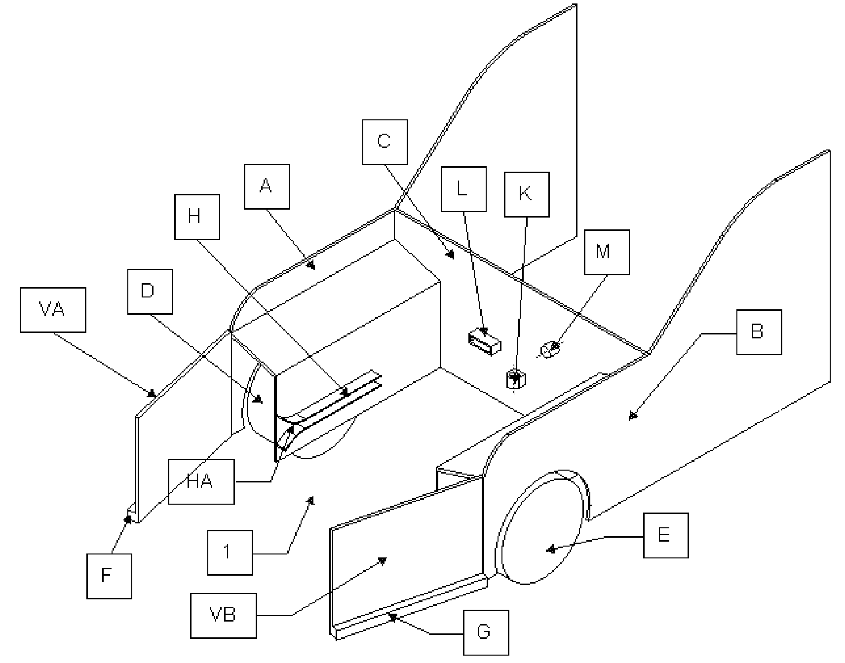
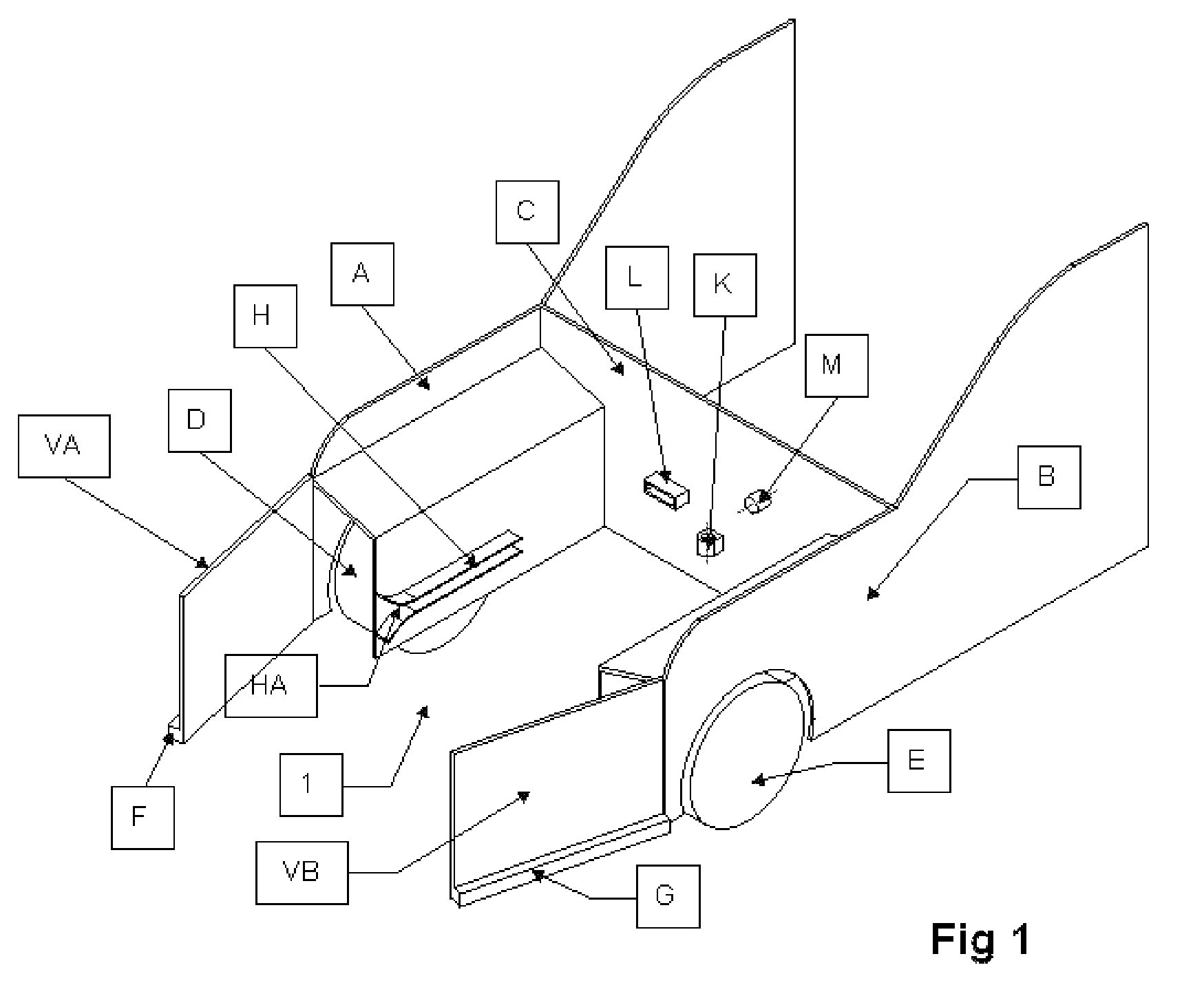
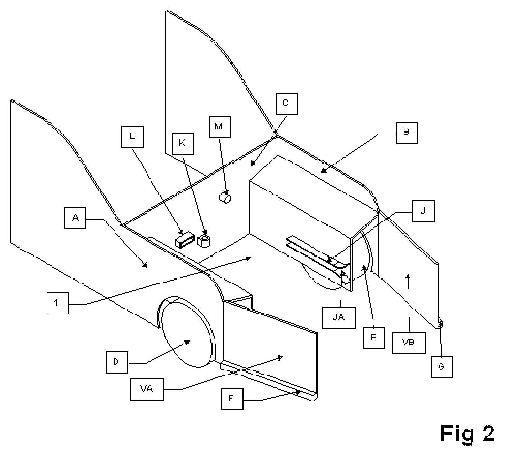
[0018]Referring to FIG. 1 and FIG. 2, the whole chamber is generally referred to as 1. Chamber 1 has a left side wall A; a right side wall B and a back wall C, together forming an enclosure for the power plant. The front wheels of the vehicle are marked D and E. The vehicle has a left front fender, F, and a right front fender, G. Fender F is connected to the left side wall A with hinges. Similarly, fender G is connected to the right side wall B with hinges. Fenders F and G meet at the center. Side walls A and B have guide rails, H and J on their inside surface. Guide rail H is mounted horizontally along the length of side wall A. Similarly, guide rail J is mounted horizontally along the length of side wall B. The guide rails have a latch such that when the power plant is pushed all the way in toward the back wall C, it will lock the power plant on the rails, thus preventing it from sliding out. The latch must be released manually to slide the power plant out. An engine mount, K, is ...


PUM


Abstract

A hybrid automobile chassis, heat engine and secondary battery are designed such that the secondary battery and the heat engine can be swapped easily to address different needs. For regular daily use, the secondary battery will be used. For long distance trips, the secondary battery is wheeled out and the heat engine wheeled in, to generate electricity that will provide motive power to the electric motors.

Description

CROSS REFERENCE TO RELATED APPLICATIONS[0001]This patent application claims priority from provisional U.S. patent application entitled “Interchangeable Power Plant for Automobiles,” having application No. 60 / 971,405 filed on Sep. 11, 2007, the contents of which are incorporated herein by reference.REFERENCE CITED[0002]U.S. Pat. No. 5,760,569—Jun. 2, 1998—Chase Jr., Robert B.U.S. Pat. No. 5,251,721—Oct. 12, 1993—Ortenheim, Bjorn A.FIELD OF INVENTION[0003]The present invention relates generally to hybrid electric vehicles that use one or more power sources to propel a vehicle. The common sources of power are the battery and the internal combustion engine. The present invention relates more particularly to methods and systems to build a vehicle in which the power plants can be changed quickly.BACKGROUND OF INVENTION[0004]In the United States, people generally drive about 30 to 60 miles per day to get to work and back. In many other countries, the distances are much less. But the manufa...

Claims


Application Information

Patent Timeline
IPC IPC(8): B60K7/00B60K1/04
CPCB60K1/04B60K6/48Y02T10/6221B62D25/082B60K2001/0455Y02T10/62
Inventor SUBRAMANIAN, NARAYANAN M.
Owner INVENTION DYNAMICS
Learn More