

Brushless electric machine
a brushless electric machine and electric motor technology, applied in the direction of electric devices, magnetic circuit rotating parts, magnetic circuit shape/form/construction, etc., can solve the problems of reducing the flexible operating characteristics of electric machines, adverse effects on the efficiency of electric machines, and unsatisfactory transformer interference effects, etc., to achieve high efficiency, reduce torque pulsation, and reduce the effect of nois
- Summary
- Abstract
- Description
- Claims
- Application Information
AI Technical Summary
Benefits of technology
Problems solved by technology
Method used
Image

Examples
first embodiment
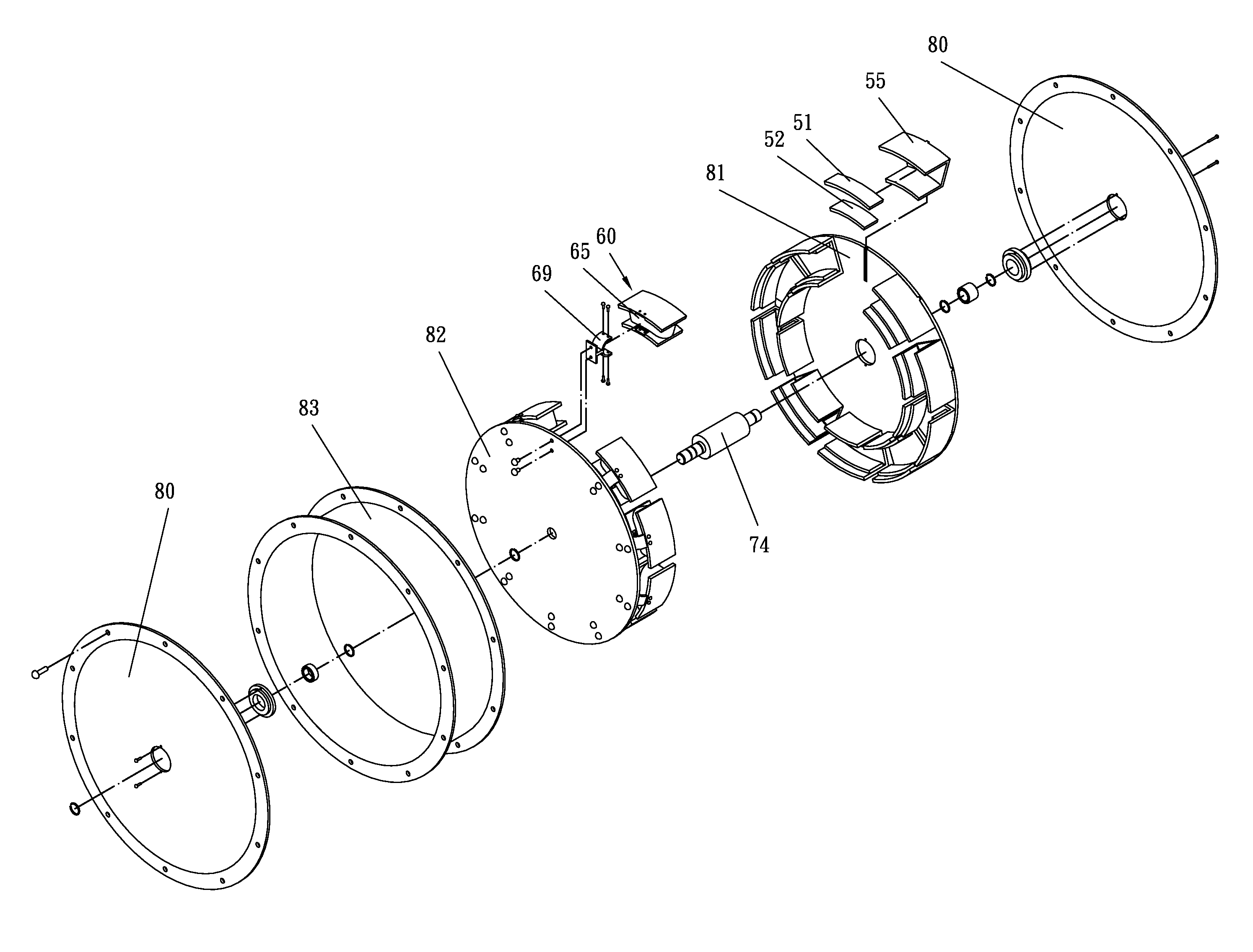
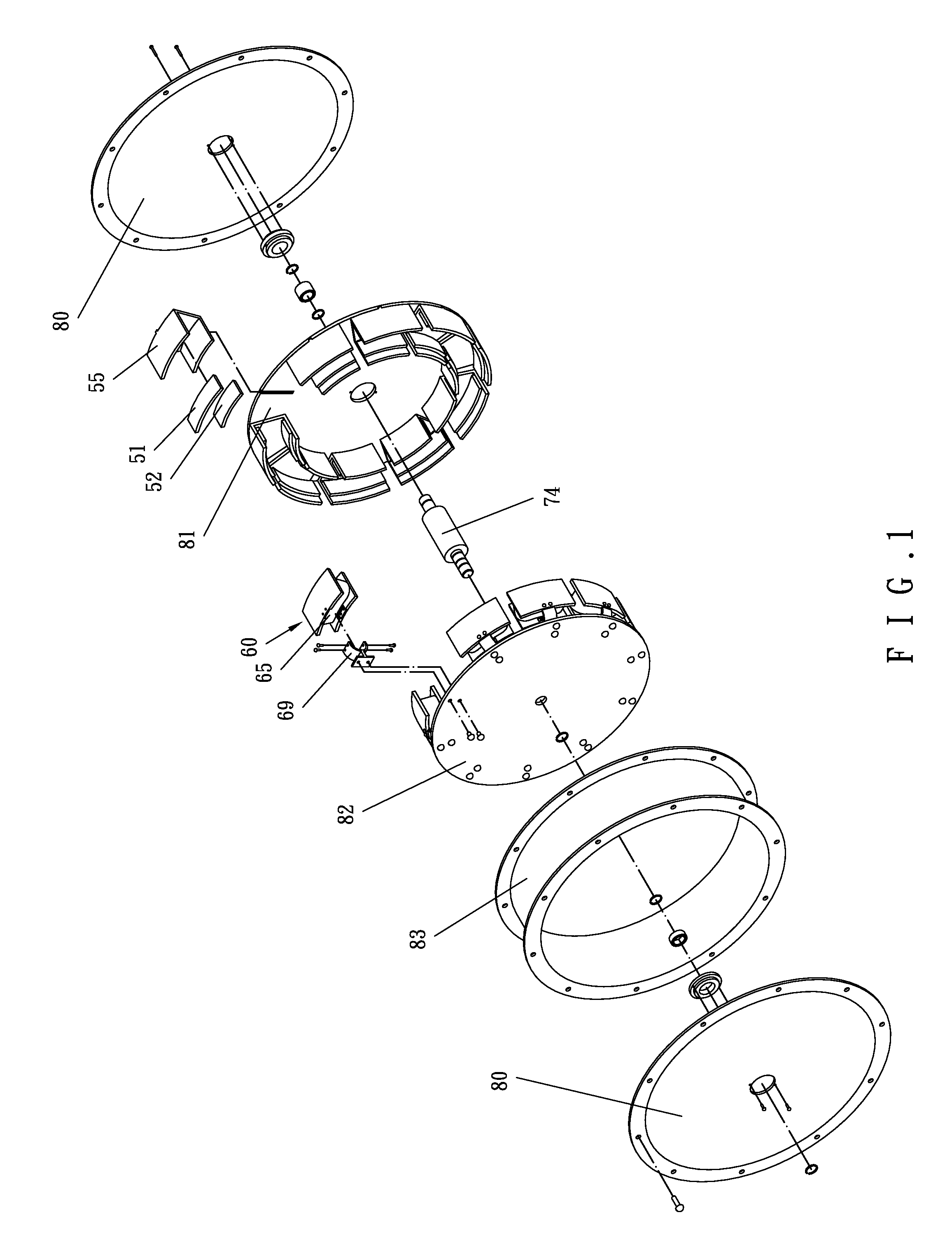
[0059]FIG. 1 is an exploded perspective view illustrating members of a brushless electric machine in accordance with the present invention. The brushless electric machine in accordance with the present invention includes a stator and a rotor. The rotor includes a plurality of magnetic elements having permanent magnets. Each magnetic element includes a substantially U-shaped coupling seat 55 made of ferromagnetic material. Permanent magnets 51 and 52 are respectively mounted to inner faces of two lateral walls of the U-shaped coupling seat 55 of each magnetic element and form two magnetic poles of the magnetic element. A rear side of the U-shaped coupling seat of each magnetic element is engaged with a rotor fixing disc 81 such that the magnetic elements having permanent magnets are arranged along a circumferential direction about a revolving shaft 74 to form a rotor wheel-shaped ring. The rotor fixing disc 81 is coupled with one of two rotor discs 80. The rotor outer ring 83 is enga...
second embodiment
[0066]FIG. 5 is a variation of a cross section of FIG. 3, illustrating the present invention. In the illustrative figures of the present invention, wherein only the elements modified are labeled with different reference numbers to allow easy understanding of the modifications among the embodiments. Compared to the electric machine of FIG. 3, the brushless electric machine of FIG. 5 affects the maximum output but allows more uniform flux distribution of a pole pair of every electromagnetic member of the stator. The pole pair of each electromagnetic member in FIG. 3 is replaced by a pole pair 61a and 62a of the same pole face area in FIG. 5. In FIG. 5, to allow more matching with the flux distribution of two permanent magnet poles of each magnetic element of the rotor, the magnetic poles of the permanent magnets 51a and 52a of each magnetic element are modified to be more symmetrical whereas the coupling seat 55a is also modified responsive to the change of the permanent magnets 51a a...
fourth embodiment
[0068]FIG. 7 is a variation of partial, exploded perspective view similar to a portion of a stator of the brushless electric machine of FIG. 1, illustrating the present invention. Each U-shaped pole 61c, 62c of a pole pair of the electromagnetic member of the stator provides a relatively large air-gap surface area to reduce the volume of the brushless electric machine and to attain a more efficient brushless electric machine. The axially facing pole faces on two sides of each U-shaped pole are axially aligned. Each U-shaped pole 61c, 62c of the electromagnetic member of the stator includes four grooves. Two grooves 611b of each U-shaped pole are located on two opposite ends of a side of the U-shaped pole whereas the other two grooves 612b of the U-shaped pole are located on two opposite ends of the other side of the U-shaped pole. Fixing plates 611 and 612 made of non-ferromagnetic material each include a protrusion 611a, 612a on each of two radial sides thereof, with the protrusion...
PUM
 Abstract
Description
Claims
Application Information