Piezoactuator

a technology of actuators and actuators, applied in piezoelectric/electrostrictive/magnetostrictive devices, piezoelectric/electrostriction/magnetostriction machines, electrical apparatus, etc., can solve the problems of complex and therefore cost-intensive manufacturing of these devices, and achieve the effects of improving the thermal conductivity of plastics, ensuring safety during transportation and assembly, and extreme media resistan

Inactive Publication Date: 2009-04-23
ROBERT BOSCH GMBH
View PDF5 Cites 3 Cited by
  • Summary
  • Abstract
  • Description
  • Claims
  • Application Information

AI Technical Summary

Benefits of technology

[0010]The invention consequently produces an inexpensive-to-manufacture piezoelectric actuator, which, as mentioned at the beginning, can be a component of a piezo injector for a fuel injection system in an internal combustion engine in which fuel flows around the plastic. The proposed casing makes the piezoelectric actuator according to the invention extremely media-resistant and also assures a safe handling during transport and assembly.
[0011]According to a particularly advantageous embodiment, protruding ends of the metallic foil converge in an extension at least in the region of the actuator foot and can therefore be tightly compressed into an essentially cylindrical form that extends further in the axial direction. In this case, it is also advantageous if a central, axial bore is provided in the actuator foot, into which the converging, united foil ends are inserted.
[0012]The plastic, which is partially elastic for the given mechanical and thermal strain in this case and is applied as a final layer, can simply be composed of a plastic extrusion coating that has solid particles mixed into it. In this instance, the plastic extrusion coating can preferably be a PA66 plastic or the like and the solid particles can be composed, for example, of metal or silicon, particularly in order to improve the thermal conductivity in the plastic.

Problems solved by technology

Of particular note in this connection is primarily the problem of sealing a coating material of the piezoelectric actuator and possibly a sleeve at the end points on an actuator foot, an actuator head, and possibly a holding body—as a rule composed of steel—to protect the arrangement from mechanical influences here as well.
The known arrangements, however, are complex and therefore cost-intensive in their manufacture.

Method used


Image

  • Piezoactuator
  • Piezoactuator
  • Piezoactuator

Examples


Embodiment Construction

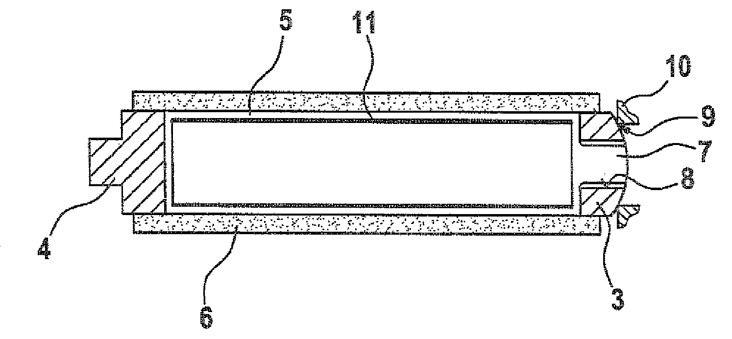
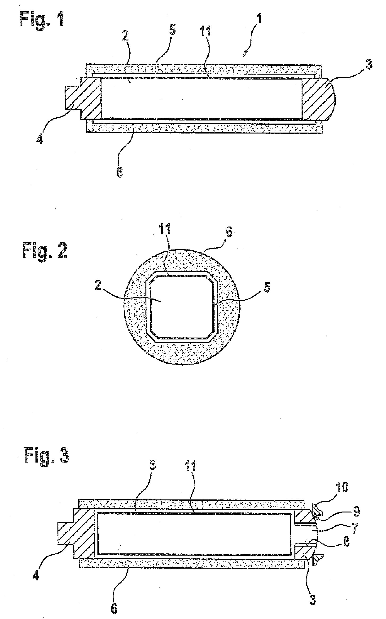
[0019]FIG. 1 shows a piezoelectric actuator 1 that can be used, for example, for needle stroke control in a fuel injection system of an internal combustion engine. A piezoelectric element 2 is a component of the piezoelectric actuator 1, which also has an actuator foot 3 and an actuator head 4, mostly composed of steel. FIG. 2 shows that the piezoelectric actuator 1 has a rectangular cross section; depending on the practical application, however, it can also have a round or otherwise adapted cross section.

[0020]The piezoelectric element 2 contains internal electrodes not explicitly shown here, which are contacted by means of external electrodes and by means of electrical supply lines, likewise not shown here, which are routed through the actuator foot 3. When the piezoelectric actuator 1 is actuated through an application of a voltage to the internal electrodes, a mechanical arrangement that is situated axially beyond the actuator head 4 in this case can be actuated in such a way th...


PUM


Abstract

A piezoactuator includes a piezoelement of a multilayer construction of piezolayers, with internal electrodes arranged between the piezolayers alternately having a differing polarity of an electrical voltage applied to them. An actuator base and an actuator head and an insulation medium surrounding at least the piezolayers of the piezoelement are present. The surface of the piezoelement is provided with a first electrical insulation layer. The piezoactuator has at least one layer of a metallic film wound around it at least in the region of the piezoelement. A layer of a plastic is applied to the film and in a manner overlying the connecting locations with respect to the actuator head and with respect to the actuator base.

Description

[0001]The invention relates to an at least partially encased piezoelectric actuator, for example around which fluid media flow, with the defining characteristics of the preamble to the main claim.PRIOR ART[0002]It is intrinsically known that the above-mentioned piezoelectric actuator can be constructed using a piezoelectric element in such a way that by utilizing the so-called piezoelectric effect it is possible to carry out a valve needle stroke control or the like. The piezoelectric element is composed of a material with a suitable crystalline structure so that when an external voltage is applied, a mechanical reaction of the piezoelectric element occurs. which, depending on the crystalline structure and the application region of the electric voltage, represents a compression or a tension in a predeterminable direction. Piezoelectric actuators of this kind are suitable, for example, for applications in which stroke motions occur with powerful actuation forces and at high clock fre...

Claims


Application Information

Patent Timeline
Patent Type & Authority Applications(United States)
IPC IPC(8): H01L41/00
CPCH01L41/0533H10N30/883
Inventor MATTES, PATRICK
Owner ROBERT BOSCH GMBH
Why Eureka
Try Eureka