Organic light emitting device and color display apparatus using the same

a technology of light emitting device and color display device, which is applied in the direction of discharge tube luminescnet screen, discharge tube/lamp details, electric discharge lamps, etc., can solve the problems of disadvantageous white light extraction and difficulty in incorporating large-area high-resolution display apparatuses

Active Publication Date: 2009-04-23
SAMSUNG DISPLAY CO LTD
View PDF10 Cites 19 Cited by
  • Summary
  • Abstract
  • Description
  • Claims
  • Application Information

AI Technical Summary

Benefits of technology

[0012]It is therefore one object of the present invention to provide an improved top-emission or bottom-emission organic light emitting display (OLED) that is free of the disadvantages above.
[0013]It is another object for the present invention to provide a top-emission or bottom-emission organic light emitting display (OLED) using color filters, in which has a wide color gamut and reduces a variation of color with a viewing angle.

Problems solved by technology

When different organic EMLs are formed in respective sub-pixels, however, it is difficult to embody large-area high-resolution display apparatuses due to a complicated fabrication process.
Since resonance caused in the resonant cavities narrows the spectrum of externally emitted light, it is advantageous at extracting only light with a specific wavelength, but it is disadvantageous at extracting white light.
Therefore, fabrication of a color display apparatus using the OLED may involve a very complicated process so that the optical thickness of the resonant cavities may be controlled to be different according to respective R, G, and B sub-pixels.

Method used


Image

  • Organic light emitting device and color display apparatus using the same
  • Organic light emitting device and color display apparatus using the same
  • Organic light emitting device and color display apparatus using the same

Examples


Embodiment Construction

[0057]The present invention will be described more fully hereinafter with reference to the accompanying drawings, in which exemplary embodiments of the invention are shown. The same reference numerals are used to denote the same elements throughout the specification. In the drawings, the thicknesses of layers and regions are exaggerated for clarity. Although a top-emitting organic light emitting display (OLED) is exemplarily illustrated in the drawings, the present invention is not limited to the top-emitting OLED and can be also applied to a bottom-emitting OLED.

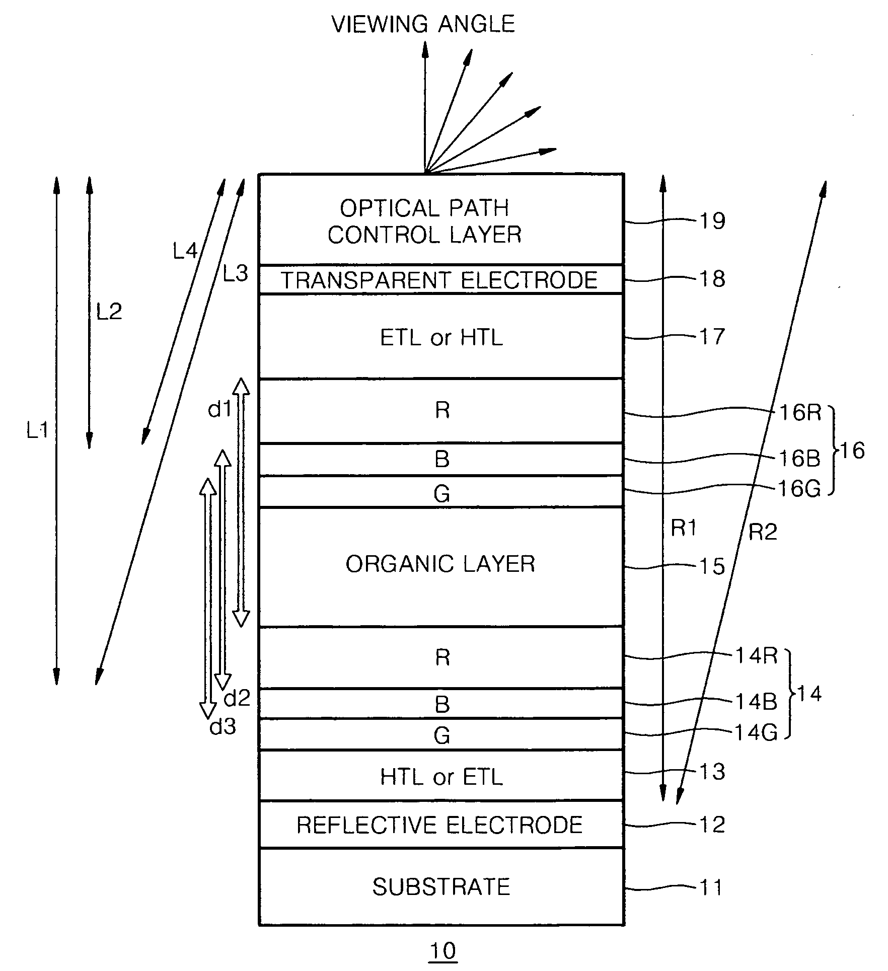
[0058]FIG. 1 is a schematic view of a top-emitting white OLED 10 constructed as an embodiment of the present invention.

[0059]Referring to FIG. 1, top-emitting white OLED 10 includes a substrate 11, a reflective electrode 12, a transmissive electrode 18, at least two organic emission layers (EMLs) 14 and 16 disposed between reflective electrode 12 and transmissive electrode 18, layers 13, 15, and 17 for emitting electrons an...


PUM


Abstract

A top-emitting or bottom-emitting OLED has a wide color gamut and reduces a variation in color with a viewing angle. The OLED includes a reflective electrode and a transmissive or semi-transmissive electrode disposed opposite each other; at least two organic emission layers (EMLs) interposed between the reflective electrode and the transmissive or semi-transmissive electrode; and an optical path control layer disposed on an outer surface of the transmissive or semi-transmissive electrode. A resonator is formed between the reflective electrode and the optical path control layer so a resonance mode of light extracted from the optical path control layer is a multi-resonance mode having at least two modes in a visible light region. A distance between the organic EMLs satisfies the condition of constructive interference between light beams emitted by the respective organic EMLs. A color display apparatus using the OLED are taught.

Description

CLAIM OF PRIORITY[0001]This application makes reference to, incorporates the same herein, and claims all benefits accruing under 35 U.S.C. §119 from an application for ORGANIC LIGHT EMITTING DEVICE AND COLOR DISPLAY APPARATUS USING THE SAME earlier filed in the Korean Intellectual Property Office on 17 Oct. 2007 and there duly assigned Serial No. 10-2007-0104477.BACKGROUND OF THE INVENTION[0002]1. Field of the Invention[0003]The present invention relates to an organic light emitting device (OLED) and a color display apparatus using the same, and more particularly, to a top-emitting or bottom-emitting OLED, which improves a color gamut and reduces a variation of color with a viewing angle, and a color display apparatus employing such improved OLED.[0004]2. Description of the Related Art[0005]In an organic light emitting device (OLED), holes from an anode combine with electrons from a cathode in an organic emission layer (EML) formed between the anode and the cathode to emit light, th...

Claims


Application Information

Patent Timeline
Patent Type & Authority Applications(United States)
IPC IPC(8): H01L27/32
CPCH01L51/5036H01L51/5278H01L51/5265H10K50/125H10K50/852H10K50/19H05B33/28H05B33/22H05B33/14
Inventor LEE, SUNG-HUNKIM, SANG-YEOLKIM, MU-GYEOMSONG, JUNG-BAE
Owner SAMSUNG DISPLAY CO LTD
Why Eureka
Try Eureka