Gas discharge tube

Active Publication Date: 2009-04-23
BOURNS INC
View PDF9 Cites 13 Cited by
  • Summary
  • Abstract
  • Description
  • Claims
  • Application Information

AI Technical Summary

Benefits of technology

[0016]The object of the present invention is to make available gas discharge tubes for all relevant areas of application, said gas discharge tubes exhibiting in par

Problems solved by technology

These are, however, not comparable to the modern surge arresters with respect to size, reliability, performance and production technology.
Thus the formation of the spark is, to a great part, based on the underlying material, which is not necessarily inert, but is due to oxidation in the existing

Method used


Image

  • Gas discharge tube
  • Gas discharge tube
  • Gas discharge tube

Examples


Example

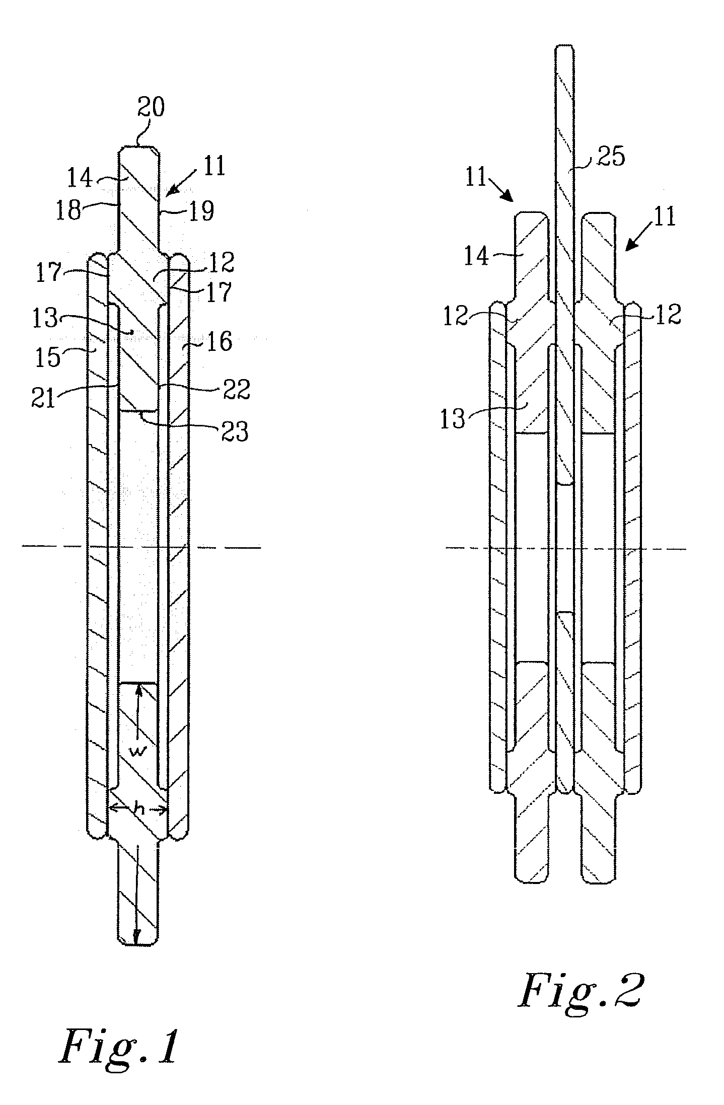
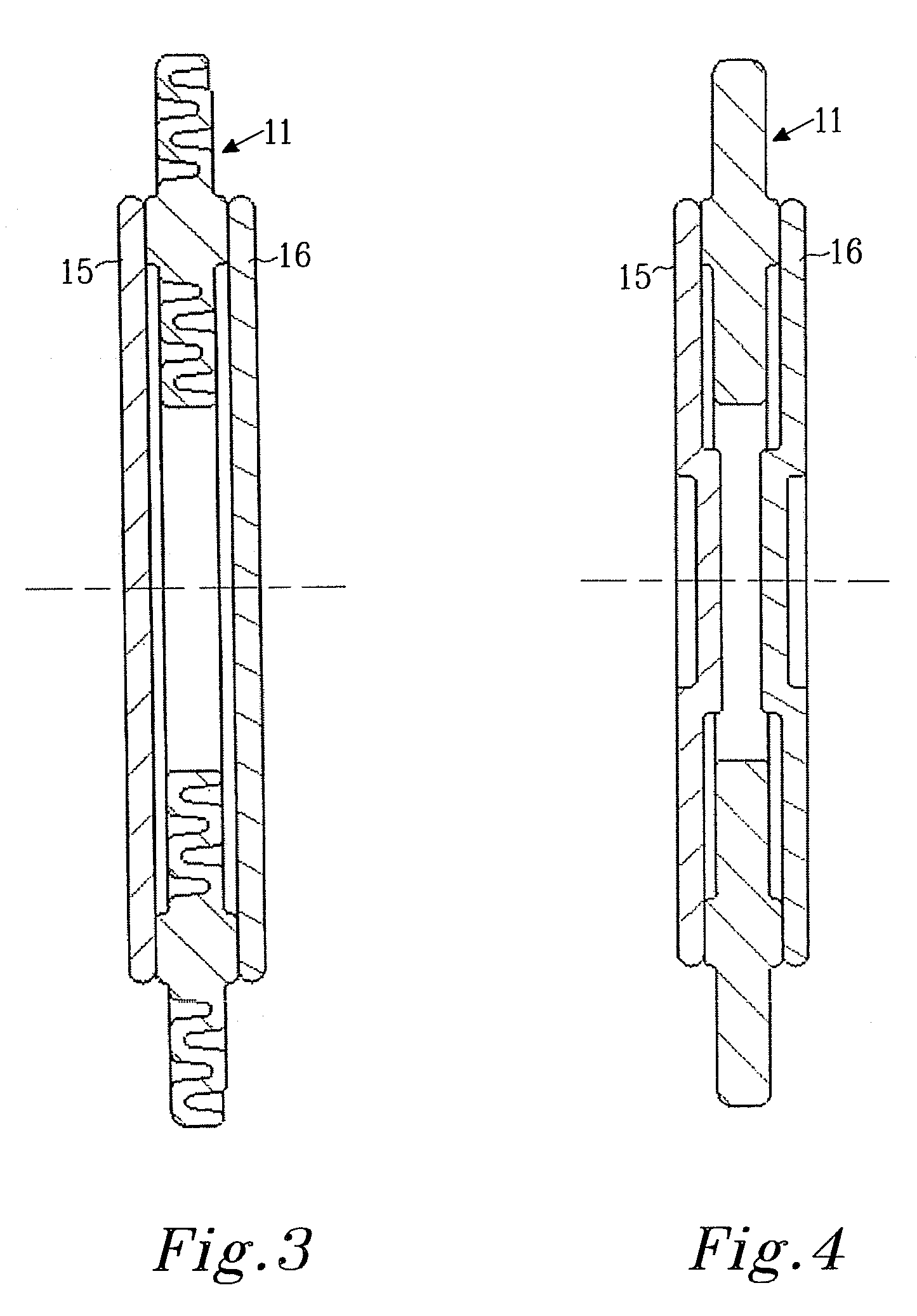
[0034]FIG. 1 shows a first embodiment of the present invention, wherein 11 denotes a ceramic ring taking any shape as defined above, known to possess electro insulating properties. The ring 11 comprises a cylindrical structure 12 from which radially extending flanges 13 and 14 extend inwardly and outwardly. Two electrodes 15 and 16 are attached by means of soldering to the end surfaces of the cylindrical part 12 of the ring. The electrodes 15 and 16 are normally made of copper, silver or gold, iron / nickel alloy, or have one or more of these metals upon their surfaces.

[0035]The insulating ring 11 comprises, as given above, a cylindrical part 12 having two planar, oppositely facing surfaces 17, which surfaces normally are preprepared to accept soldering metals, such as tin and tin alloys or hard soldering alloys. Further the ceramic ring 11 comprises one outwardly, radially extending flange 13 having two radially extending surfaces 18 and 19 forming an angle to the cylindrical part 12...


PUM


Abstract

A new gas discharge tube comprising at least two electrodes and at least one hollow insulator ring fastened to at least one of the electrodes, wherein the insulating ring has an extended length for a creeping current on at least one of the surfaces inside and/or outside compared to its height thereby providing a long distance to any possible creeping current.

Description

PRIORITY INFORMATION[0001]The present application claims priority to Swedish Application No. 0701246-1, filed on May 22, 2007, which is incorporated herein by reference in its entirety.DESCRIPTION[0002]1. Technical Field[0003]The present invention concerns the field of gas discharge tubes including surge arresters, gas arresters, high-intensity discharge tubes, spark gaps, switching spark gaps and triggered spark gaps, used in various applications, such as surge voltage protectors for communications networks voltage controlled switching of capacitive discharge circuits and in particular to a new type of such devices which exhibit higher selectivity, better performance and are more environmentally friendly. In particular the present invention relates to the design of an insulating part of such a gas discharge tube.[0004]2. Background of the Invention[0005]When electronic equipment is connected to long signal or power lines, antenna etc, it is exposed to transients generated by induct...

Claims


Application Information

Patent Timeline
IPC IPC(8): H01J61/02
CPCH01T4/12
Inventor SCHLEIMANN-JENSEN, JOHANNILSSON, JAN-AKESCHLEIMANN-JENSEN, ARNE
Owner BOURNS INC
Why Eureka
Try Eureka