Baffle board for base station antenna and base station antenna array structure

a technology of array structure and base station antenna, which is applied in the direction of antenna couplings, antenna details, antennas, etc., can solve the problems of large thickness of the array of base station antennas, many soldering points, and design occupies too much space, and achieves less welding, good consistency, and simple assembly

Active Publication Date: 2017-12-14
GUANGZHOU SIGTENNA TECH CO LTD
View PDF2 Cites 10 Cited by
  • Summary
  • Abstract
  • Description
  • Claims
  • Application Information

AI Technical Summary

Benefits of technology

[0019]Benefit of this application: the phase shift cavity and the reflecting plate as claimed in this application are designed in an integrative structure, having good consistency, less welding and simple assembly, costing less time and fewer raw materials, thus achieving high efficiency and low cost, simplifying the production of antennas.

Problems solved by technology

It should be noted that radiation device of a conventional reflecting plate is arranged on one side of the plate, one or more phase shifters on the other whose installation needs an independent hollow box stabilized on the plate by supporting pillars, resulting in great thickness of the base station antenna array.
During installation the correct ones must be picked from the many different cables and soldered to the right positions respectively, quality of welding machine having to be guaranteed as well, the greatest disadvantage of this design lying in that there are two many sorts of cables of different lengths and too many soldering points each of which is uncontrollable during manufacturing process.
A buffer zone must be planned for the soldering junctions to protect coaxial cables, and minimal bending radius must be planned when winding section lines, which design takes up too much space.

Method used


Image

  • Baffle board for base station antenna and base station antenna array structure
  • Baffle board for base station antenna and base station antenna array structure
  • Baffle board for base station antenna and base station antenna array structure

Examples


embodiment one

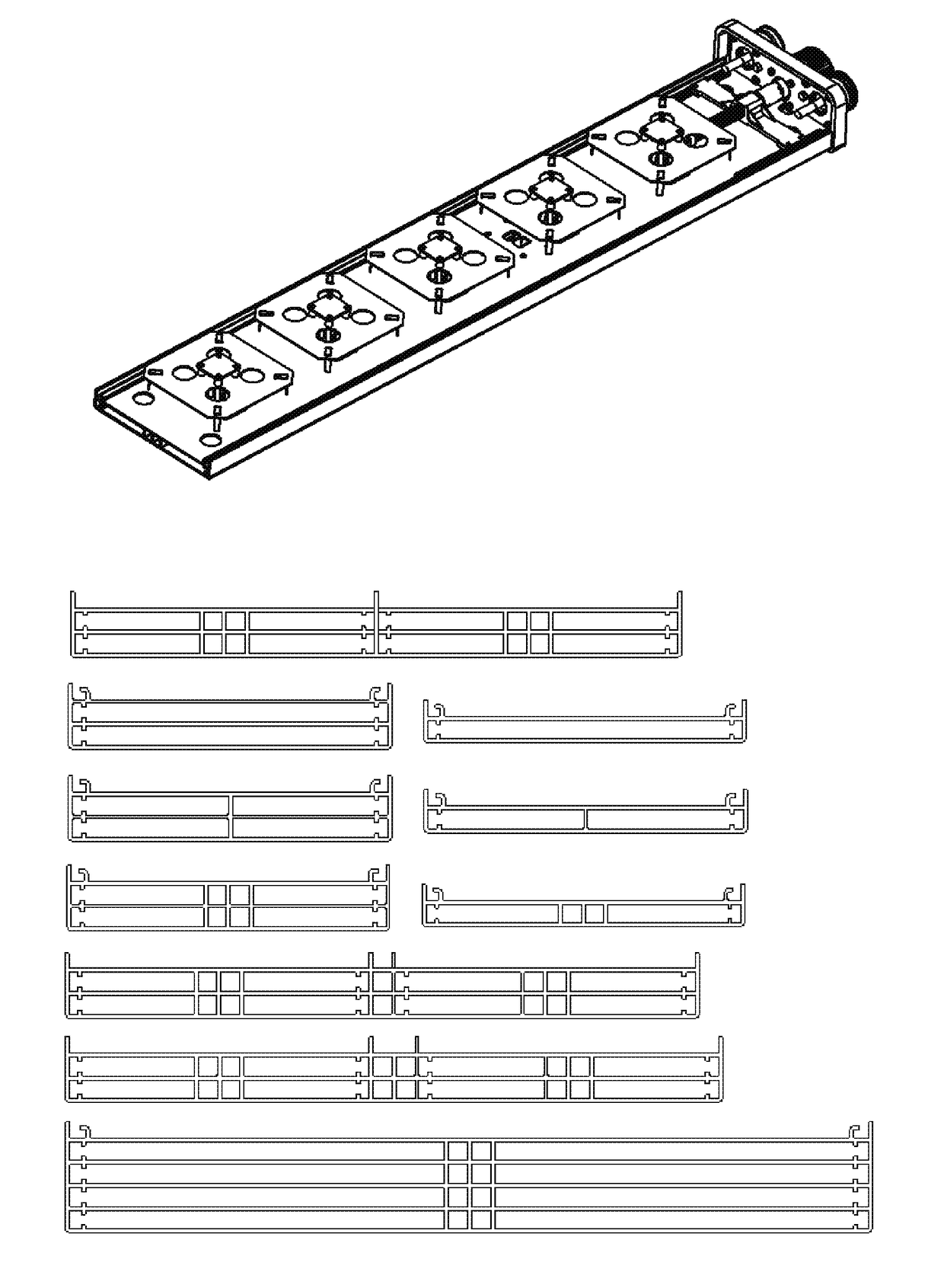
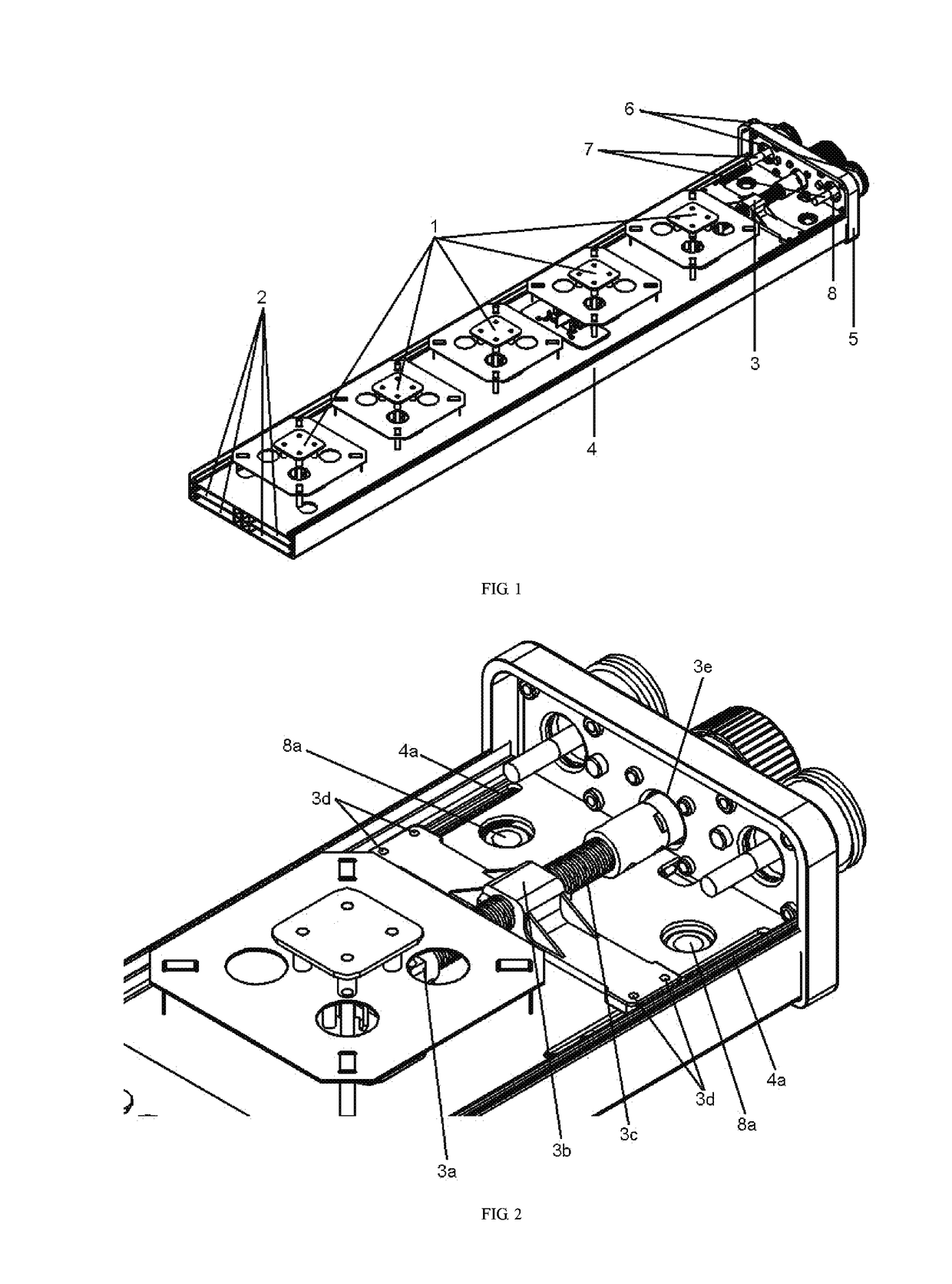
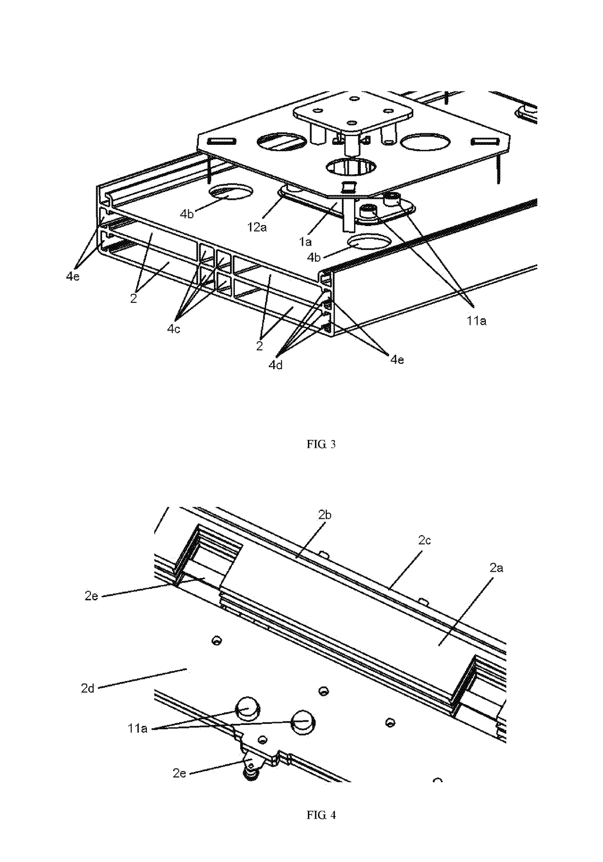
[0033]The base station antenna array structure is shown in FIGS. 1-4, as shown in FIG. 1, comprising a group of radiation devices 1, phase shifters 2, a drive mechanism 3, a reflecting plate 4, an end closure 5, joints 6, cables 7, an adaptor plate 8. The reflecting plate 4 is smaller than existing antenna reflecting plates. As can be seen from the FIGS, the reflecting plate 4 is designed to be an integrative structure of double-layer cavity, inside each of which is positioned with a phase shifter 2 whose design responds to the cavity. The group of radiation devices 1 is fixedly positioned on the reflecting plate by fasteners 11. The drive mechanism 3 is positioned on the antenna reflecting plate surface in order to save space of the back of the antenna and reduce the thickness of the antenna as a result. The adaptor plate 8, made from die-cast zinc-aluminum alloys, is positioned inside the cavity and fixedly positioned on the reflecting plate by fasteners 8a which connect a bracket...

embodiment two

[0037]The base station antenna array as claimed in this application as shown in FIG. 5, adopting single-layer cavity structure. Other designs are exactly the same with that illustrated in embodiment one, so the description will not be repeated again here.

[0038]In this embodiment, the antenna would be smaller in size due to the utilization of single-layer cavity structure.

embodiment three

[0039]This is a further study on the reflecting plate structure based on embodiment one and two, and the result reflects, as FIG. 6, the reflecting plate can be designed as single-, double- or multilayer structure according to different needs. Projection can be positioned on the reflecting plate surface in accordance with the installation of the drive mechanism to help the drive mechanism to slide accurately.

[0040]Respecting to the reflecting plate and the corresponding base station antenna array structure as claimed in this application, the phase shift cavity is designed to be an integrative structure with the reflecting plate, characterized in good consistency, few soldering, easy installing, high efficiency, and costing fewer raw materials, thus low-cost. In addition, in the base station antenna array structure, the adaptor plate is designed to be an integrative structure with the reflecting plate, which also decrease soldering points and is easy to assemble. This technology can ...


PUM


Abstract

This application discloses a type of reflecting plate and base station array for base station antennas. The main part of the reflecting plate is mono- or multi-layer reflector chamber, the inside of each layer placed with at least one phase shift cavity, guide groove and projection, the phase shift cavity for holding components of the phase shifter, while guide groove and projection for fixing them, allowing removable dielectric insulation medium of the phase shifter to move within the guide groove. The reflecting plate and the phase shift cavity are designed in integrative structure, achieving good consistency, less soldering and easy installation, costing less time and fewer raw materials, and high efficiency and low cost as well.

Description

TECHNICAL FIELD[0001]This application relates to base station antenna technology for mobile communications, particularly a type of reflecting plate designed for base station antenna and base station array structure designed for the reflecting plate.BACKGROUND OF THE TECHNOLOGY[0002]With the rapid development of modern mobile communications, more requirements are raised for base station antennas, particularly for bandwidth characteristics and miniaturization. Downsizing in antennas becomes more demanding due to the great density of networks and public increasing sensitivity towards electromagnetic wave pollution. In addition, such engineering factors as wind resistance and convenience for installation also require reduction in size of antennas.[0003]A base station antenna is made up primarily of reflecting plate, drive mechanism, radiation unit and feed network, the reflecting plate having the ability to improve electromagnetic wave characteristics, particularly beam characteristics,...

Claims


Application Information

Patent Timeline
Patent Type & Authority Applications(United States)
IPC IPC(8): H01Q15/14H01Q1/24H01Q21/00H01Q1/52H01Q3/34H01Q3/32
CPCH01Q15/148H01Q1/528H01Q21/00H01Q3/34H01Q3/32H01Q1/246H01P1/184H01Q1/523H01Q21/0006H01Q21/08H01Q25/001H01Q15/14
Inventor SLEDKOV, VICTOR ALEKSANDROVICHLI, ZI-MENG
Owner GUANGZHOU SIGTENNA TECH CO LTD
Why Eureka
Try Eureka