Matching of gmr sensors in a bridge

a technology of gmr sensors and bridges, applied in the field of magnetic field sensors, can solve the problems of poor layout and non-informalities in the fabrication process and operating environment, the variation of geometrical shapes, and the inability to meet the needs of the user, so as to reduce the variation caused by the closest neighbor

Active Publication Date: 2009-04-23
ALLEGRO MICROSYSTEMS INC
View PDF23 Cites 38 Cited by
  • Summary
  • Abstract
  • Description
  • Claims
  • Application Information

AI Technical Summary

Benefits of technology

[0010]Particular implementations of the invention may provide one or more of the following advantages. Dummy MR elements can provide symmetry to the bridge circuit layout where such symmetry might otherwise be lacking. Symmetry in the MR elements near an activ

Problems solved by technology

Thus, a critical design challenge involves the variability of the individual devices built on the IC.
Sources of mismatch include variation in geometrical shapes, poor layout and non-informalities

Method used


Image

  • Matching of gmr sensors in a bridge
  • Matching of gmr sensors in a bridge
  • Matching of gmr sensors in a bridge

Examples


Embodiment Construction

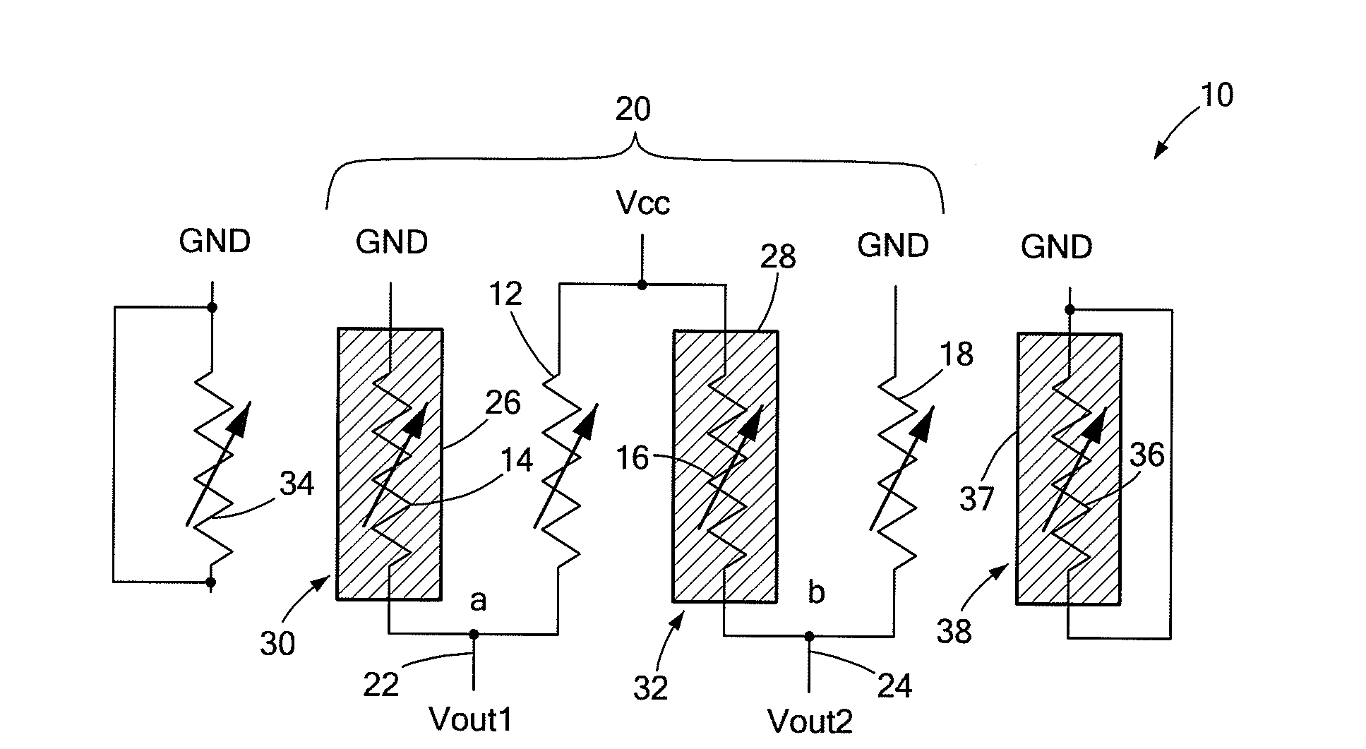
[0019]Resistor mismatch can be a serious problem in the design of resistive bridge circuits that require resistors in the bridge to have the same value. This is especially true in the case of bridge circuits used in magnetoresistive (MR) sensors. An MR sensor is a magnetic field sensor that makes use of the MR effect, the property of a current carrying material to change its resistance in the presence of an external magnetic field. The MR type resistors or “magnetoresistors” of the sensor's bridge circuit, referred to herein as MR elements, are very sensitive to the stray magnetic field effects of neighboring MR elements. Neighboring interactions can result in variations in an MR element's electrical behavior. Any variation, however small, can limit sensitivity and overall accuracy of the MR sensor. The circuits of an MR sensor, like other types of circuits, are also affected by non-uniformities introduced by a particular process during device fabrication. Often the processing-relat...


PUM


Abstract

A magnetoresistive (MR) sensing device includes MR elements electrically connected to form a bridge circuit and one or more non-functional (or “dummy”) MR elements for improved matching of the bridge circuit MR elements.

Description

CROSS-REFERENCE TO RELATED APPLICATIONS[0001]Not applicable.STATEMENT REGARDING FEDERALLY SPONSORED RESEARCH[0002]Not applicable.FIELD OF THE INVENTION[0003]This invention relates generally to magnetic field sensors, and more particularly, to the design of magnetic field sensors that use magnetoresistive (MR) elements to sense an external magnetic field.BACKGROUND OF THE INVENTION[0004]In analog integrated circuit (IC) design, it is important to use matched devices, that is, devices designed to have the same electrical properties, to achieve highly accurate circuit performance. Thus, a critical design challenge involves the variability of the individual devices built on the IC. Sources of mismatch include variation in geometrical shapes, poor layout and non-informalities in fabrication process and operating environment. Fabrication processing non-uniformity may be introduced by, for example, mask misalignment and non-uniform etching.[0005]Certain types of devices are very sensitive ...

Claims


Application Information

Patent Timeline
IPC IPC(8): G01R33/09G01B7/30
CPCG01R33/093B82Y25/00G01R15/205
Inventor DOOGUE, MICHAEL C.TAYLOR, WILLIAM P.
Owner ALLEGRO MICROSYSTEMS INC
Why Eureka
Try Eureka