Doherty amplifier
a technology of amplifiers and amplifiers, applied in amplifiers, amplifier types, amplifiers with semiconductor devices/discharge tubes, etc., can solve the problems of reducing efficiency of power amplifiers and consuming currents remarkably, and achieves the effects of reducing circuit size, high efficiency, and maintaining linearity
- Summary
- Abstract
- Description
- Claims
- Application Information
AI Technical Summary
Benefits of technology
Problems solved by technology
Method used
Image
Examples
first embodiment
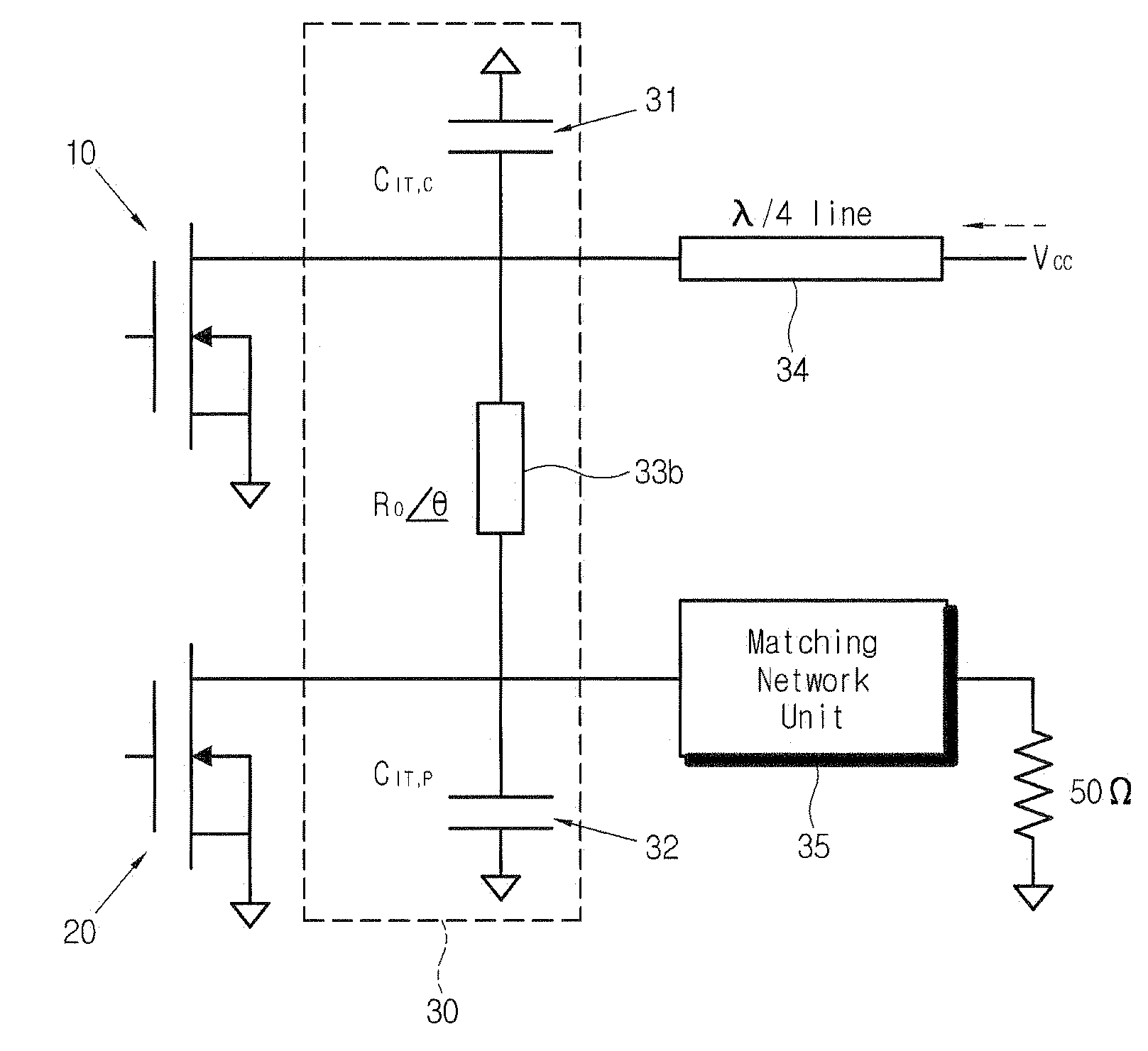
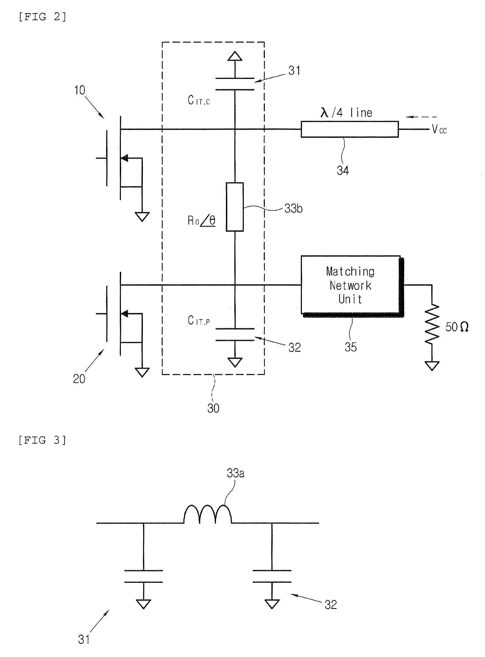
[0027]FIG. 2 is a diagram illustrating the construction of the Doherty amplifier in accordance with the present invention. As shown in the drawing, the Doherty amplifier in accordance with the present invention includes a main amplifying unit 10, an auxiliary amplifying unit 20 and a compact λ / 4 line 30.
[0028]The Doherty amplifier in accordance with the present invention improves entire efficiency of the Doherty amplifier by applying biases different from each other to the main amplifying unit 10 and the auxiliary amplifying unit 20 respectively or through an automatic bias control.
[0029]The compact λ / 4 line 30 is connected to the output sides of the main amplifying unit 10 and the auxiliary amplifying unit 20 and connected to a λ / 4 line 34 and a matching network unit 35. The compact λ / 4 line 30 in accordance with the present invention, as shown in FIG. 2 to FIG. 4, may include a first parallel capacitor 31, a second parallel capacitor 32 and a pair of transmission line units 33a an...
second embodiment
[0036]The first parallel impedance (jX′) 231 and the second parallel impedance (jX″) 232 are grounded by being connected to the main amplifying unit 10 and the auxiliary amplifying unit 20 in parallel respectively. A combination unit of capacitor and transmission line 236 connects the main amplifying unit 10 and the auxiliary amplifying unit 20, wherein the combination unit of capacitor and transmission line 236 in accordance with the present invention includes a capacitor as one example and may be constructed by combining a capacitor and a transmission line.
[0037]The first λ / 4 line 233 is divided between the first parallel impedance (jX′) 231 and the combination unit of capacitor and transmission line 236 and the second λ / 4 line 235 is divided between the second parallel impedance (jX″) 232 and the combination unit of capacitor and transmission line 236, respectively being used for a voltage input unit of the main amplifying unit 10 and the auxiliary amplifying unit 20. The matchin...
fourth embodiment
[0044]Hereafter, referring to FIG. 7, the Doherty amplifier is described in accordance with the present invention in detail.
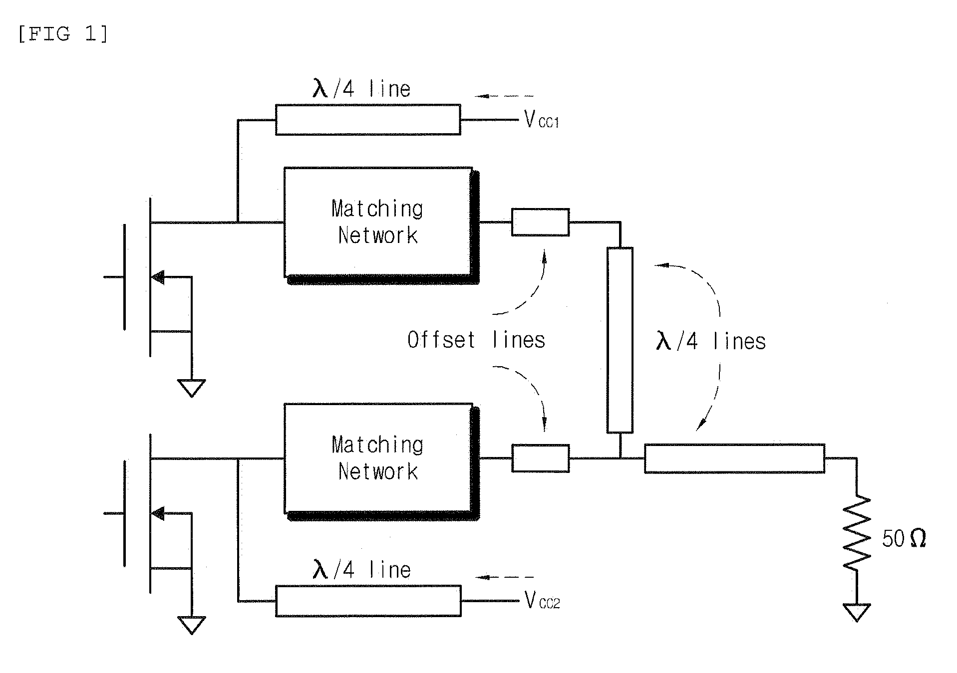
[0045]The Doherty amplifier in accordance with the fourth embodiment of the present invention includes a first matching network unit 110a, a second matching network unit 110b, a quarter-wave transmission line 130, a first offset line 120a and a second offset line 120b.
[0046]The first matching network unit 110a is connected to the output stage of the main amplifying unit 10 and matched so that the output of the main amplifying unit 10 is an impedance of 100Ω and the second matching network unit 110b is connected to the output stage of the auxiliary amplifying unit 20 and matched so that the output of the auxiliary amplifying unit 20 is an impedance of 100Ω.
[0047]The quarter-wave transmission line 130 connects the main amplifying unit 10 and the auxiliary amplifying unit 20 in parallel by being connected to the outputs of the first matching network unit 110a and...
PUM
 Abstract
Description
Claims
Application Information
 - R&D
- Intellectual Property
- Life Sciences
- Materials
- Tech Scout
- Unparalleled Data Quality
- Higher Quality Content
- 60% Fewer Hallucinations
Browse by: Latest US Patents, China's latest patents, Technical Efficacy Thesaurus, Application Domain, Technology Topic, Popular Technical Reports.
© 2025 PatSnap. All rights reserved.Legal|Privacy policy|Modern Slavery Act Transparency Statement|Sitemap|About US| Contact US: help@patsnap.com


