Optical waveguide for touch panel and touch panel using the same

a technology of optical waveguides and touch panels, applied in optical waveguide light guides, instruments, computing, etc., can solve the problems of narrowing down the emitted light beams, reducing the size of the light-receiving region too much, and low optical transmission efficiency, so as to achieve the effect of appropriate optical transmission efficiency and easy light beam reception

Inactive Publication Date: 2009-04-23
NITTO DENKO CORP
View PDF6 Cites 35 Cited by
  • Summary
  • Abstract
  • Description
  • Claims
  • Application Information

AI Technical Summary

Benefits of technology

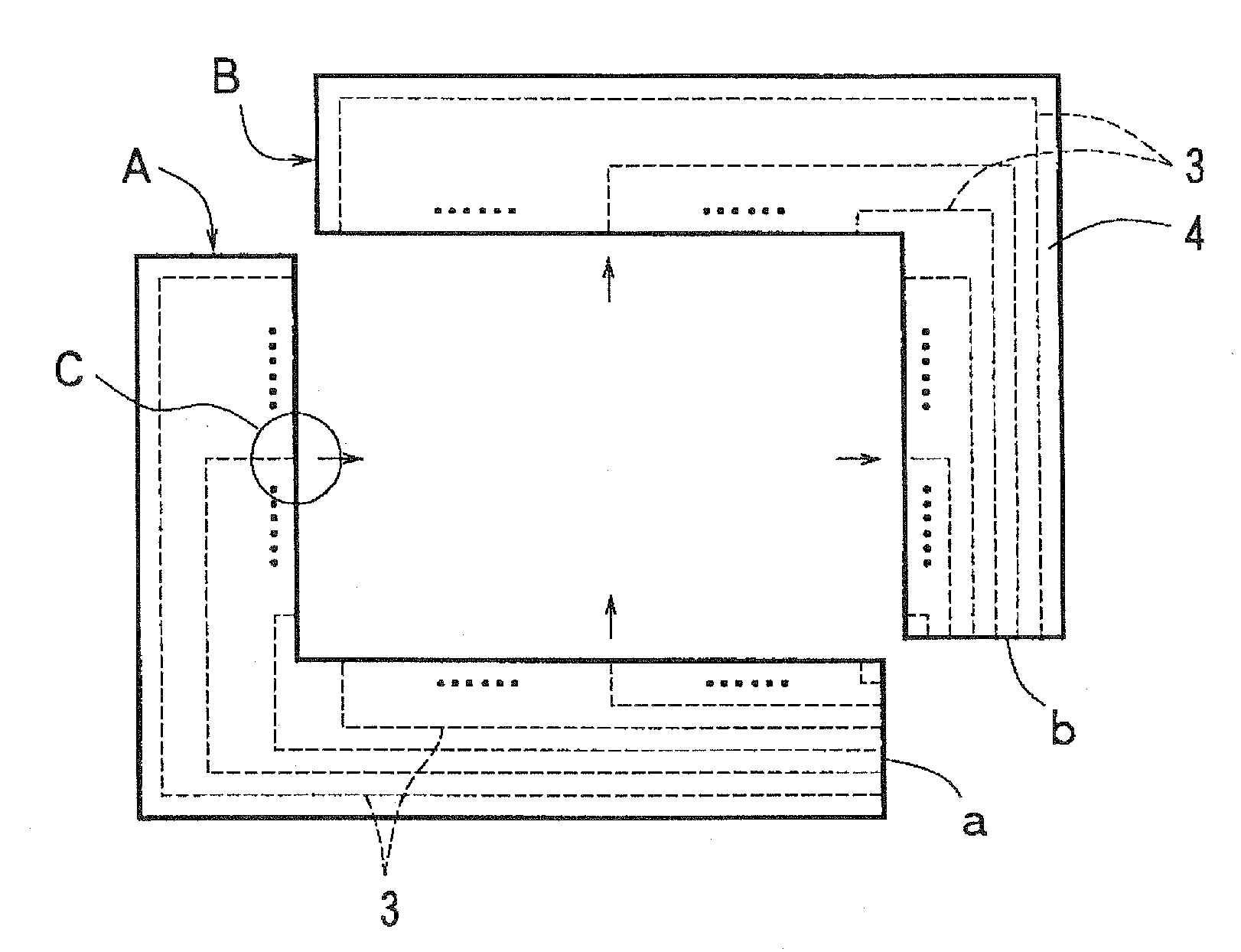
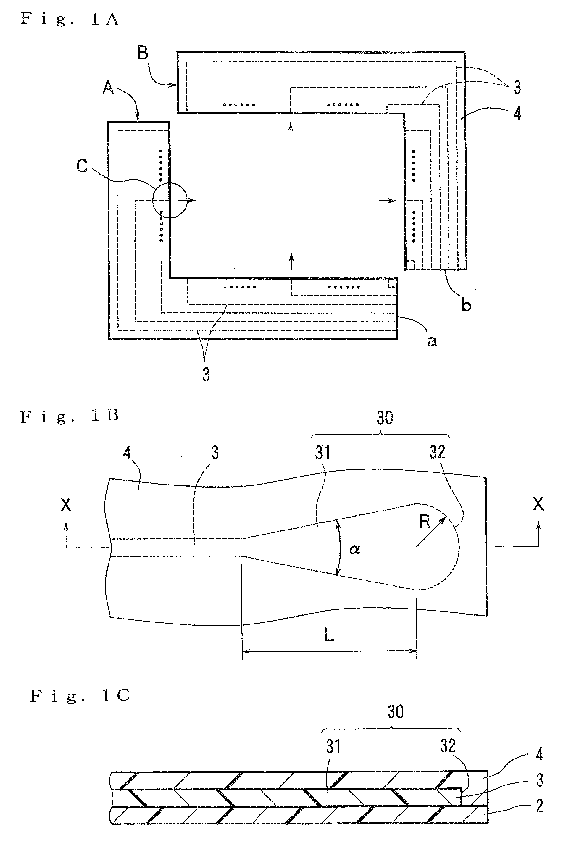
[0019]To overcome the above-mentioned problems, the present inventor has made studies of the configuration of the lens portion formed in the end portion of each core and the like. As a result, the present inventor has discovered that, when the lens portion has a tapered portion such that the width thereof gradually increases toward the end surface thereof which in turn is formed as the arcuately curved surface in plan view which bulges outwardly and the length (L) of the above-mentioned tapered portion, the taper angle (α) and the radius (R) of curvature of the arcuately curved surface in plan view satisfy the above-mentioned conditions (a) to (c) or (d) to (f), the horizontal divergence (the divergence as seen in plan view) of the light beams emitted from the end portion of each core is suppressed by refraction through the above-mentioned lens portion so that the light-receiving region has an appropriate area (neither too wide nor too narrow). Further, the present inventor has discovered that the end surface of the light-receiving core is wide and easily receives the light beams because of the configuration of the above-mentioned lens portion. Thus, the present inventor has attained the present invention.
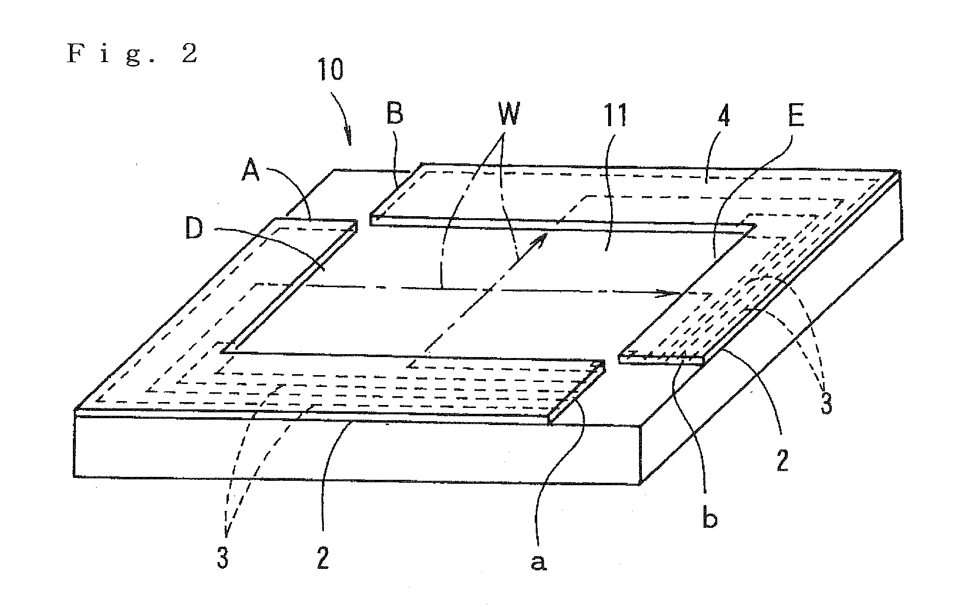
[0020]In the optical waveguide for the touch panel according to the first and second aspects of the present invention, each of the end portion of the light-emitting core and the end portion of the light-receiving core is formed as the lens portion having the above-mentioned specific configuration and specific dimensions. Thus, the light beams emitted from the end portion of the core are appropriate in divergence by refraction through the above-mentioned lens portion, and the light beams incident on the end portion of the core easily enter the core because of the configuration of the above-mentioned lens portion. As a result, the optical waveguide for the touch panel achieves optical transmission between the light-emitting core and the light-receiving core with appropriate optical transmission efficiency.

Problems solved by technology

In this case, when the emitted light beams spread too wide, there is a low probability that the light beans enter the core of the light-receiving optical waveguide, which results in low optical transmission efficiency.
However, narrowing down the emitted light beams reduces the size of a light-receiving region too much and makes it difficult for the core of the light-receiving optical waveguide to receive the light beams (or makes it impossible for the core of the light-receiving optical waveguide to receive the light beams if the core of the light-receiving optical waveguide is deviated from its proper position even slightly).

Method used


Image

  • Optical waveguide for touch panel and touch panel using the same
  • Optical waveguide for touch panel and touch panel using the same
  • Optical waveguide for touch panel and touch panel using the same

Examples


##ventive examples 1 to 18

Inventive Examples 1 to 18 and Comparative Examples 1 to 10

Material for Formation of Under Cladding Layer and Over Cladding Layer

[0063]A material for formation of an under cladding layer and an over cladding layer was prepared by mixing 35 parts by weight of bisphenoxyethanol fluorene glycidyl ether (component A) represented by the following general formula (1), 40 parts by weight of 3′,4′-epoxycyclohexylmethyl-3,4-epoxycyclohexane carboxylate which is an alicyclic epoxy resin (CELLOXIDE 2021P manufactured by Daicel Chemical

Industries, Ltd.)(Component B), 25 parts by weight of (3′,4′-epoxycyclohexane)methyl-3′,4′-epoxycyclohexyl-carboxylate(CELLOXIDE 2081 manufactured by Daicel Chemical Industries, Ltd.) (Component C), and 2 parts by weight of a 50% propione carbonate solution of 4,4′-bis[di(β-hydroxyethoxy)phenylsultinio]phenyl-sulfide-bis-hexafluoroantimonate (component D).

wherein R1 to R6 are hydrogen atoms, and n=1.

Material for Formation of Cores

[0064]A material for formation of...


PUM


Abstract

An optical waveguide for a touch panel and a touch panel using the same. A lens portion 30 formed in an end portion of each light-emitting core 3 and each light-receiving core 3 has a tapered portion 31 such that the width thereof gradually increases toward an end surface thereof. The end surface is an arcuately curved surface 32 which bulges outwardly and has a radius of curvature R. When the tapered portion 31 has a length L not less than 800 μm, a taper angle α is in the range of 2 to 20 degrees, and (A) is satisfied. When the tapered portion 31 has a length L not less than 400 μm but less than 800 μm, the taper angle α is in the range of 4 to 16 degrees, and condition (A) is satisfied.
(A)0.5×L×tan(α/2)<R<2.5×L×tan(α/2).

Description

RELATED APPLICATIONS[0001]This application claims the benefit of U.S. Provisional Application No. 60 / 985,725, filed Nov. 6, 2007, which is hereby incorporated by reference.BACKGROUND OF THE INVENTION[0002]1. Field of the Invention[0003]The present invention relates to an optical waveguide fox a touch panel and a touch panel using the same.[0004]2. Description of the Related Art[0005]Touch panels are input devices for operating an apparatus by directly touching a display screen of a liquid crystal display device or the like with a finger, a purpose-built stylus or the like, and include a display which displays operation details and the like, and a detection means which detects the position (coordinates) of a portion of the display screen of the display touched with the finger or the like. Information about the touch position detected by the detection means is sent in the form of a signal to the apparatus, which in turn performs an operation and the like displayed on the touch positio...

Claims


Application Information

Patent Timeline
Patent Type & Authority Applications(United States)
IPC IPC(8): G06F3/042
CPCG06F3/0421G02B6/00G06F3/0304G06F3/0412
Inventor JUNI, NORIYUKI
Owner NITTO DENKO CORP
Why Eureka
Try Eureka