Light guide plate

a technology of light guide plate and guide plate, which is applied in the direction of lighting and heating apparatus, instruments, mechanical equipment, etc., can solve the problems of uneven brightness on the light exit plane, increased machining costs, and lower light use efficiency of backlight units than direct illumination types, so as to increase weight and cost, uneven brightness, and increase thickness

Inactive Publication Date: 2009-04-23
FUJIFILM CORP
View PDF19 Cites 32 Cited by
  • Summary
  • Abstract
  • Description
  • Claims
  • Application Information

AI Technical Summary

Benefits of technology

[0010]Also proposed is a method whereby the light guide plate is provided with a reflection member near its light entrance plane on the opposite side from the light entrance plane to cause admitted light to undergo multiple reflection before allowing the light to exit through the light exit plane. To achieve a large light exit plane with these light guide plates by this method, however, the light guide plate needs to have an increased thickness, increasing weight and costs. Further, the light sources are projected into the light guide plate and perceived as such to cause uneven brightness and / or uneven illuminance.
[0011]An object of the present invention is to provide a light guide plate having a flat shape, yielding a high light use efficiency, capable of emitting light with a minimized unevenness in brightness and achieving a high-in-the-middle or bell-curve brightness distribution such that a central area of the screen is brighter than the periphery, thereby overcoming the problems associated with the prior art described above.
[0030]The present invention achieves a large and thin light guide plate yielding a high light use efficiency, emitting light with a minimized unevenness in brightness and illuminance and a high-in-the-middle or bell-curve brightness distribution whereby the central area of the light exit plane is bright as compared with the periphery.

Problems solved by technology

However, those backlight units yielded lower light use efficiency than the direct illumination type because of the relative dimensions of the cold cathode tube to the reflector.
Further, where the light guide plate used is shaped to have grooves for receiving cold cathode tubes, although such a light guide plate could be shaped to have a thickness that decreases with the increasing distance from the cold cathode tube, if the light guide plate is made thinner, brightness at locations immediately above the cold cathode tube disposed in the grooves increased, thus causing uneven brightness on the light exit plane to stand out.
In addition, all these light guide plates posed further problems: complex configurations leading to increased machining costs.
Thus, a light guide plate of any of such types adapted to be used for a backlight unit for a large liquid crystal television having a screen size of say 37 inches or larger, in particular 50 inches or larger, was considerably expensive.
To achieve a large light exit plane with these light guide plates by this method, however, the light guide plate needs to have an increased thickness, increasing weight and costs.
Further, the light sources are projected into the light guide plate and perceived as such to cause uneven brightness and / or uneven illuminance.

Method used


Image

  • Light guide plate
  • Light guide plate
  • Light guide plate

Examples


Embodiment Construction

[0047]Now, a planar lighting device using the light guide plate according to the invention will be described in detail referring to the preferred embodiments illustrated in the attached drawings.

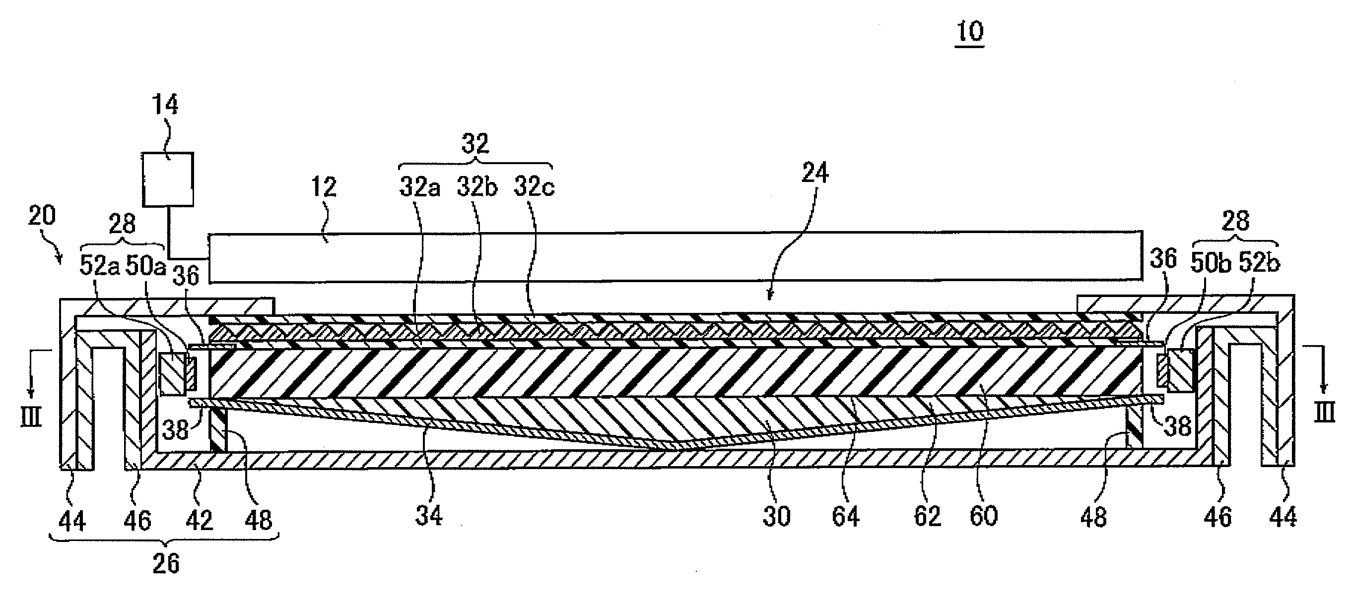
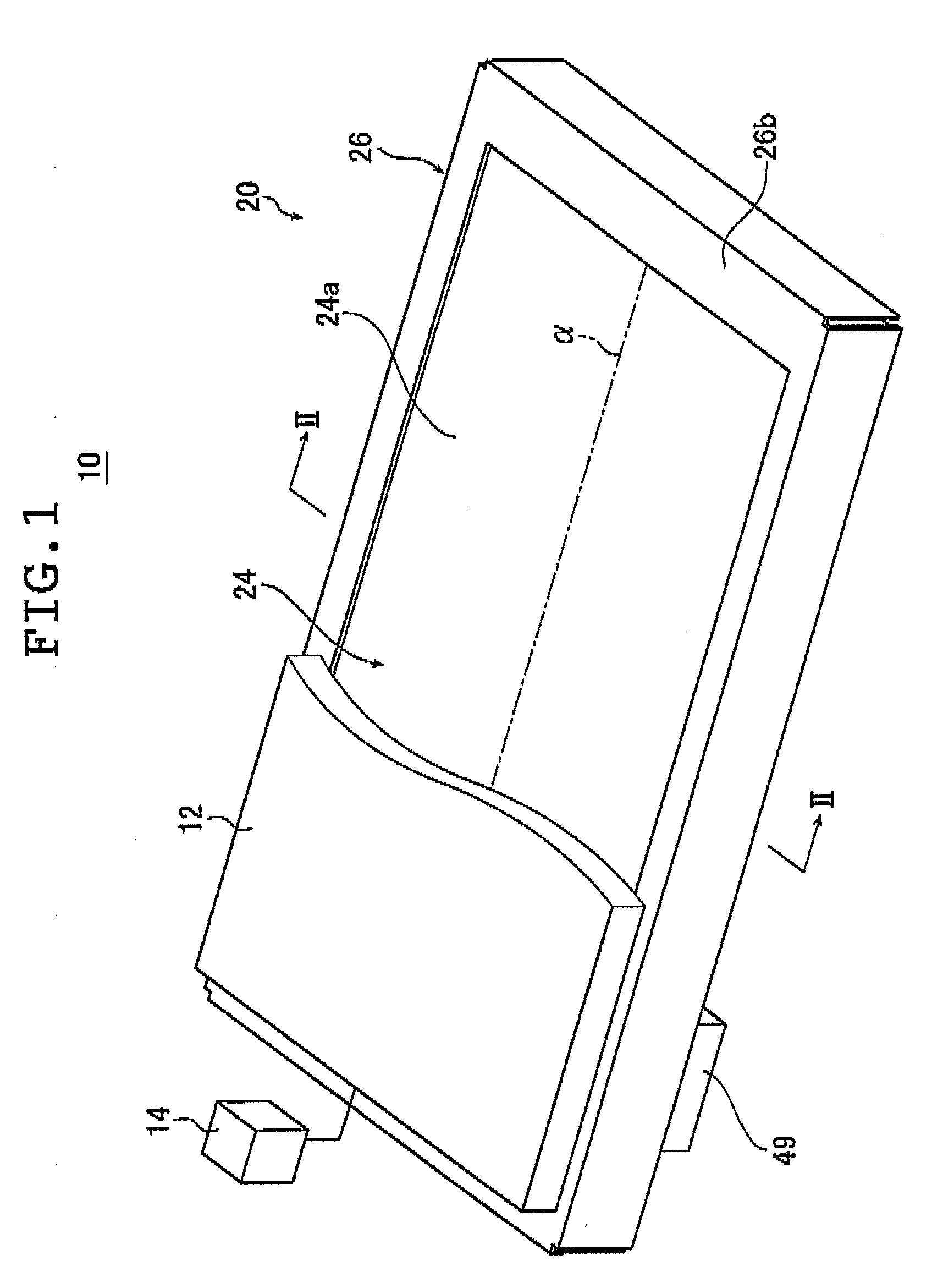
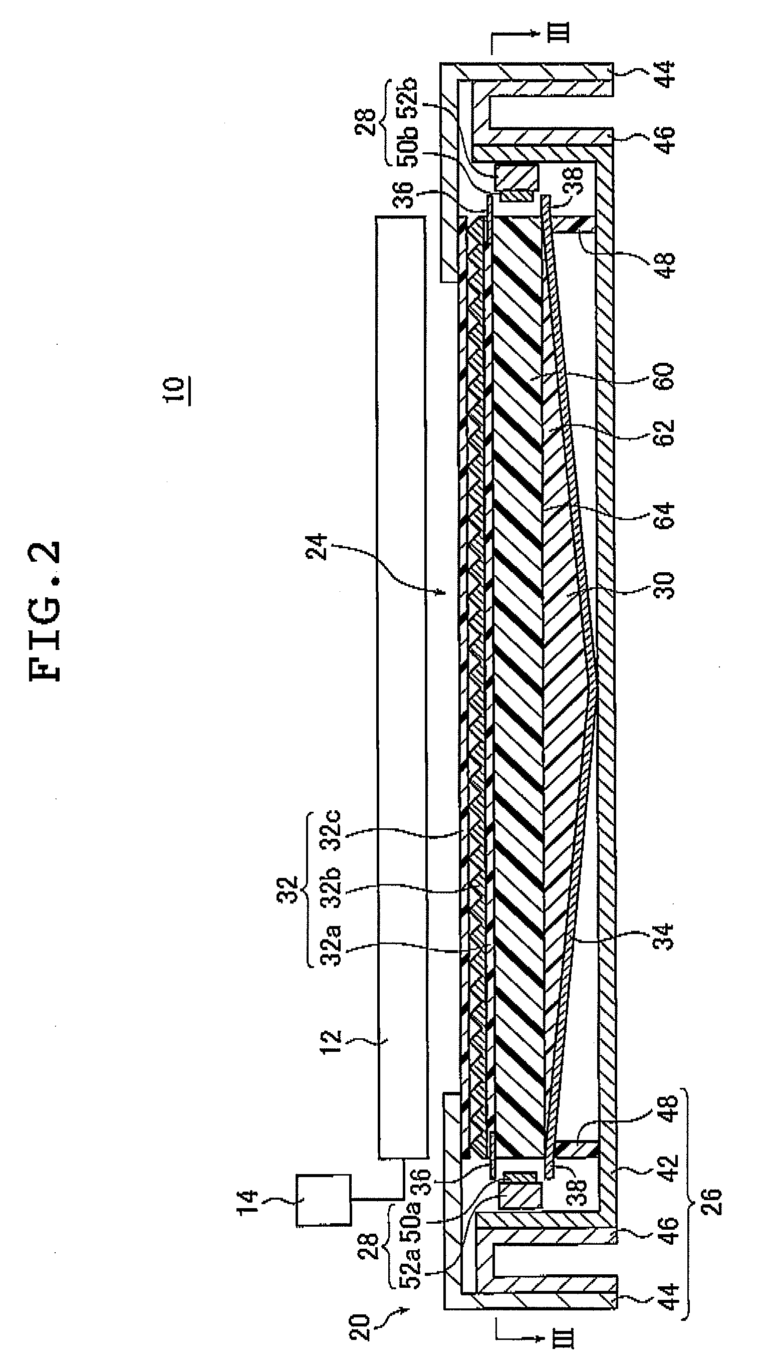
[0048]FIG. 1 is a schematic perspective view illustrating a liquid crystal display device provided with a planar lighting device using the light guide plate according to the invention; FIG. 2 is a cross sectional view of the liquid crystal display device illustrated in FIG. 1 taken along line II-II.

[0049]FIG. 3A is a view of an example of the planar lighting device (also referred to as “backlight unit” below) illustrated in FIG. 2 taken along line III-III; FIG. 3B is a cross sectional view of FIG. 3A taken along line B-B.

[0050]A liquid crystal display device 10 comprises a backlight unit 20, a liquid crystal display panel 12 disposed on the side of the backlight unit-closer to the light exit plane, and a drive unit 14 for driving the liquid crystal display panel 12. In FIG. 1, part of the li...


PUM


Abstract

The light guide plate includes a rectangular light exit plane, a light entrance plane containing one side of the light exit plane, and a rear plane located on the side opposite from the light exit plane and scattering particles for scattering light propagating inside the light guide plate dispersed therein. The light guide plate has two layers, a first layer located on the side closer to the light exit plane and having a first particle density of the scattering particles, and a second layer located on the side opposite from the light exit plane and having a second particle density that is greater than the first particle density of the first layer. Npo and Npr satisfy Npo<Npr, where Npo is the first particle density and Npr is the second particle density.

Description

[0001]The entire contents of documents cited in this specification are incorporated herein by reference.BACKGROUND OF THE INVENTION[0002]The present invention relates to a light guide plate used for liquid crystal display devices and the like.[0003]Liquid crystal display devices use a backlight unit for radiating light from behind the liquid crystal display panel to illuminate the liquid crystal display panel. A backlight unit is configured using a light guide plate for diffusing light emitted by an illuminating light source to irradiate the liquid crystal display panel and optical parts such as a prism sheet and a diffusion sheet for rendering the light emitted from the light guide plate uniform.[0004]Currently, large liquid crystal televisions predominantly use a so-called direct illumination type backlight unit comprising a light guide plate disposed immediately above the illuminating light source (seer for example, JP 05-4133 U). This type of backlight unit comprises a plurality...

Claims


Application Information

Patent Timeline
Patent Type & Authority Applications(United States)
IPC IPC(8): F21V8/00
CPCG02B6/0046G02B6/0041
Inventor IWASAKI, OSAMUNAGANO, HIDEO
Owner FUJIFILM CORP
Why Eureka
Try Eureka