Method for treating tissue

a tissue and tissue technology, applied in the field of tissue treatment, can solve the problems of stray rf flow in collateral tissues that may be undesirable, tissue desiccation or charring at the electrode-tissue interface, and high “controllability

Inactive Publication Date: 2009-04-23
TSUNAMI MEDTECH
View PDF100 Cites 128 Cited by
  • Summary
  • Abstract
  • Description
  • Claims
  • Application Information

AI Technical Summary

Benefits of technology

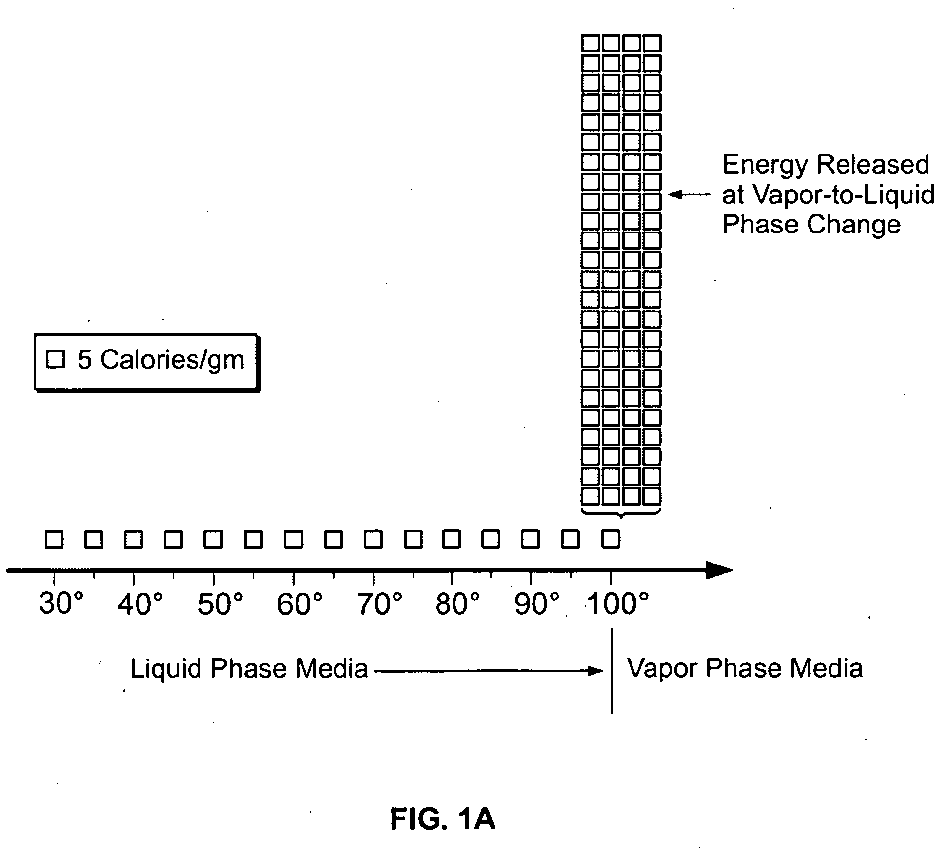
[0033]FIG. 1A is an illustration of a prior art laser-induced thermal weld effect in two approximated tissue layers.
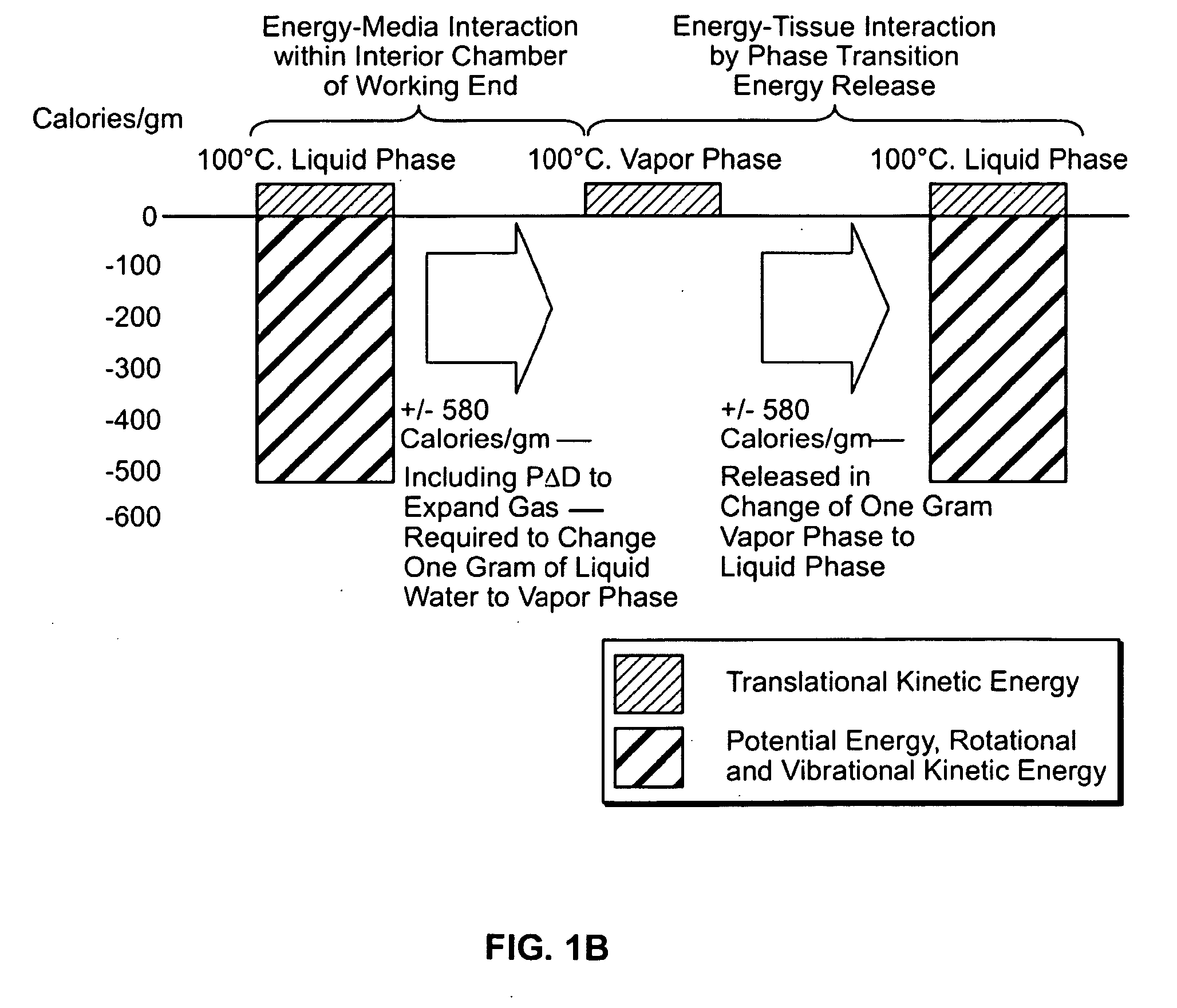
[0034]FIG. 1B is an illustration of a prior art radiofrequency energy induced thermal weld effect in two approximated tissue layers.

Problems solved by technology

The tissue is elevated in temperature by it resistance to current flow, resulting typically in tissue desiccation or charring d at the electrode-tissue interface.
Further, the prior art Rf energy delivery of FIG. 1B causes stray Rf flow in collateral tissues that may be undesirable.
While such prior art forms of energy delivery work well for some applications, Rf and laser energy typically cannot cause highly “controlled” and “localized” thermal effects that are desirable in microsurgeries or other precision surgeries.

Method used


Image

  • Method for treating tissue
  • Method for treating tissue
  • Method for treating tissue

Examples


Embodiment Construction

1. Type “A” System for Tissue Fusion

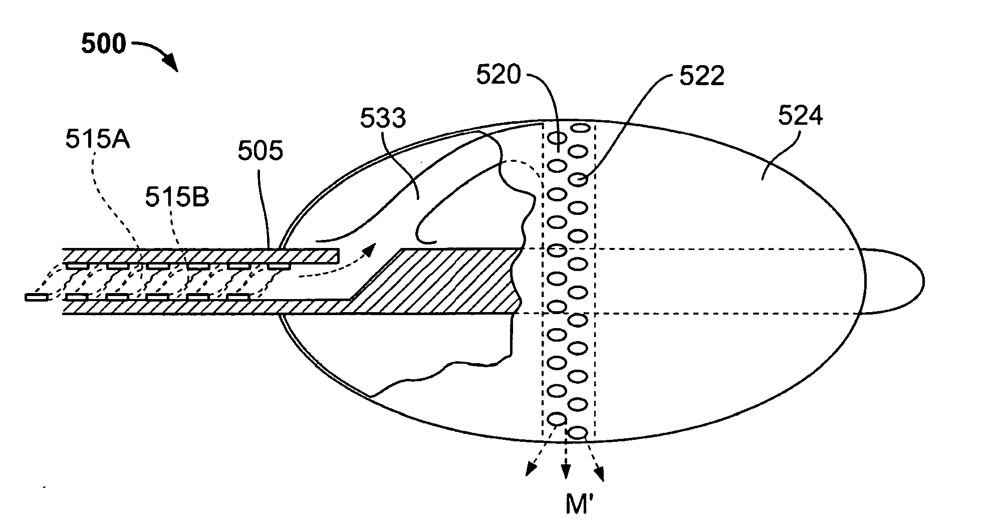
[0073]Referring to FIGS. 3A-3B and FIG. 4, the working end 10 of a Type “A” system 5 of the present invention is shown that is adapted for endoscopic procedures in which a tissue volume t targeted for fusion (a thermoplasty) can be captured by a loop structure. The working end 10 comprises a body 11 of insulator material (see FIG. 4) coupled to the distal end of introducer member 12 extending along axis15. In this exemplary embodiment, the working end 10 has a generally cylindrical cross-section and is made of any suitable material such as plastic, ceramic, glass, metal or a combination thereof. The working end 10 is substantially small in diameter (e.g., 2 mm. to 5 mm.) and in this embodiment is coupled to an elongate flexible introducer member 12 to cooperate with a working channel in an endoscope. Alternatively, the working end 10 may be coupled to a rigid shaft member having a suitable 5 mm. to 10 mm. diameter to cooperate with a standard troc...


PUM


Abstract

This invention relates to a novel surgical device scalable to small dimensions for thermally-mediated treatments or thermoplasties of targeted tissue volumes. An exemplary embodiment is adapted for fusing, sealing or welding tissue. The instruments and techniques utilize a thermal energy delivery means, for example an electrical energy source, to instantly elevate the temperature of a biocompatible fluid media within an electrically insulated instrument portion. The altered media which may then be a gas is characterized by a (i) a high heat content, and (ii) a high exit velocity from the working end, both of which characteristics are controlled to hydrate tissue and at the same time denature proteins to fuse, seal, weld or cause any other thermally-mediated treatment of an engaged tissue volume—while causing limited collateral thermal damage and while totally eliminating electrical current flow the engaged tissue volume. The system can further utilize a piezoelectric material that carried fluid channels to apply compressive forces to the fluid eject the fluid from the working end of make it require less electrical energy to convert it to a gas.

Description

CROSS-REFERENCE TO RELATED APPLICATIONS[0001]This application is a continuation of U.S. patent application Ser. No. 10 / 830,372 filed on Apr. 22, 2004, which claims the benefit of U.S. Provisional Application No. 60 / 464,935 filed Apr. 22, 2003 and is a continuation-in-part of U.S. patent application Ser. No. 10 / 017,582 filed Dec. 7, 2001, now U.S. Pat. No. 6,669,694, which claims benefit of Provisional U.S. Patent Application No. 60 / 254,487 filed Dec. 9, 2000. This application is also a continuation-in-part of U.S. patent application Ser. No. 10 / 681,625 filed Oct. 7, 2003 which claims the benefit of Provisional U.S. Patent Application No. 60 / 416,622. The contents of the above applications are incorporated herein by reference in their entirety.BACKGROUND OF THE INVENTION[0002]This invention relates to a novel surgical device scalable to small dimensions for thermally-mediated treatments or thermoplasties of targeted tissue volumes. An exemplary embodiment is adapted for fusing, sealin...

Claims


Application Information

Patent Timeline
Patent Type & Authority Applications(United States)
IPC IPC(8): A61B18/04A61B17/00
CPCA61B18/04A61B18/18A61B18/1815A61B18/20A61B2218/005A61B2018/00619A61B2018/0063A61B2018/048A61B2017/00504
Inventor SHADDUCK, JOHN H.
Owner TSUNAMI MEDTECH
Why Eureka
Try Eureka