Methods and systems for digitally controlled multi-frequency clocking of multi-core processors

a multi-core processor and multi-frequency clocking technology, applied in the field of computer system clocking, can solve the problems of inability to scale, and inability to achieve long-term strategy, and achieve the effect of improving power managemen

Active Publication Date: 2009-04-23
IBM CORP
View PDF18 Cites 40 Cited by
  • Summary
  • Abstract
  • Description
  • Claims
  • Application Information

AI Technical Summary

Benefits of technology

[0007]Embodiments of the invention include a method for digitally controlled multi-frequency clocking. The method includes receiving a system reference oscillator clock frequency at a microprocessor including multiple cores. The system reference oscillator clock frequency provides a reference frequency to a local oscillator. The local oscillator supplies a core clock frequency to at least one of the cores. The method further includes adjusting the local oscillator to output the core clock frequency at a frequency greater than the system reference oscillator clock frequency as a function of digital frequency characteristic data associated with the core or cores. The method supports extendibility to larger systems and may support enhanced power management through frequency adjustments at the core level.

Problems solved by technology

Computer systems, such as servers, have encountered technology limitations associated with scaling performance by continuing to increase processor clock frequency.
The increasing difficulty and hardware cost, as well as signal integrity concerns, associated with the transmission of high frequency clocking throughout a multi-chip and multi-core processor computer system make this an untenable long-term strategy for future systems.
This technique is limited in scalability due to skin effect, media and connector loss, crosstalk, termination mismatches, and the like.
Transmission of high frequency clocks (>5-10 GHz) for multiple chips, with multiple cores, in server systems is not feasible with known board technology and connectors.
Obtaining optimum performance for each core within a multi-core system is not feasible today.
Separate core fixed voltage domains are known, but they can only serve to optimize the power at the chip level and not obtain optimum chip performance.

Method used


Image

  • Methods and systems for digitally controlled multi-frequency clocking of multi-core processors
  • Methods and systems for digitally controlled multi-frequency clocking of multi-core processors
  • Methods and systems for digitally controlled multi-frequency clocking of multi-core processors

Examples


Embodiment Construction

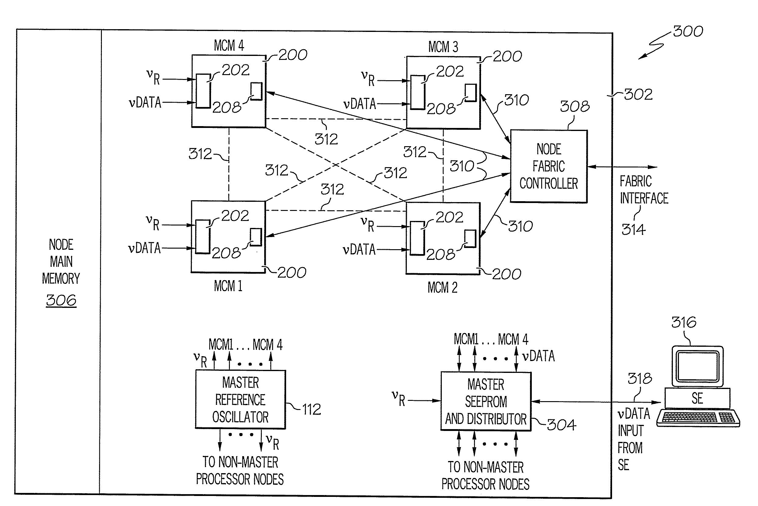
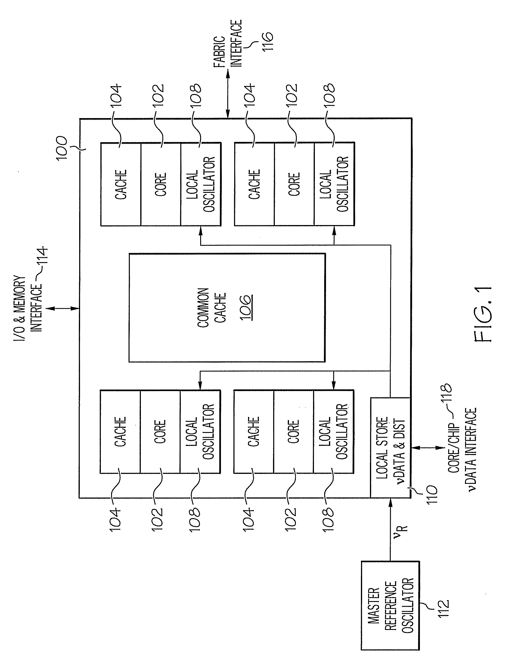
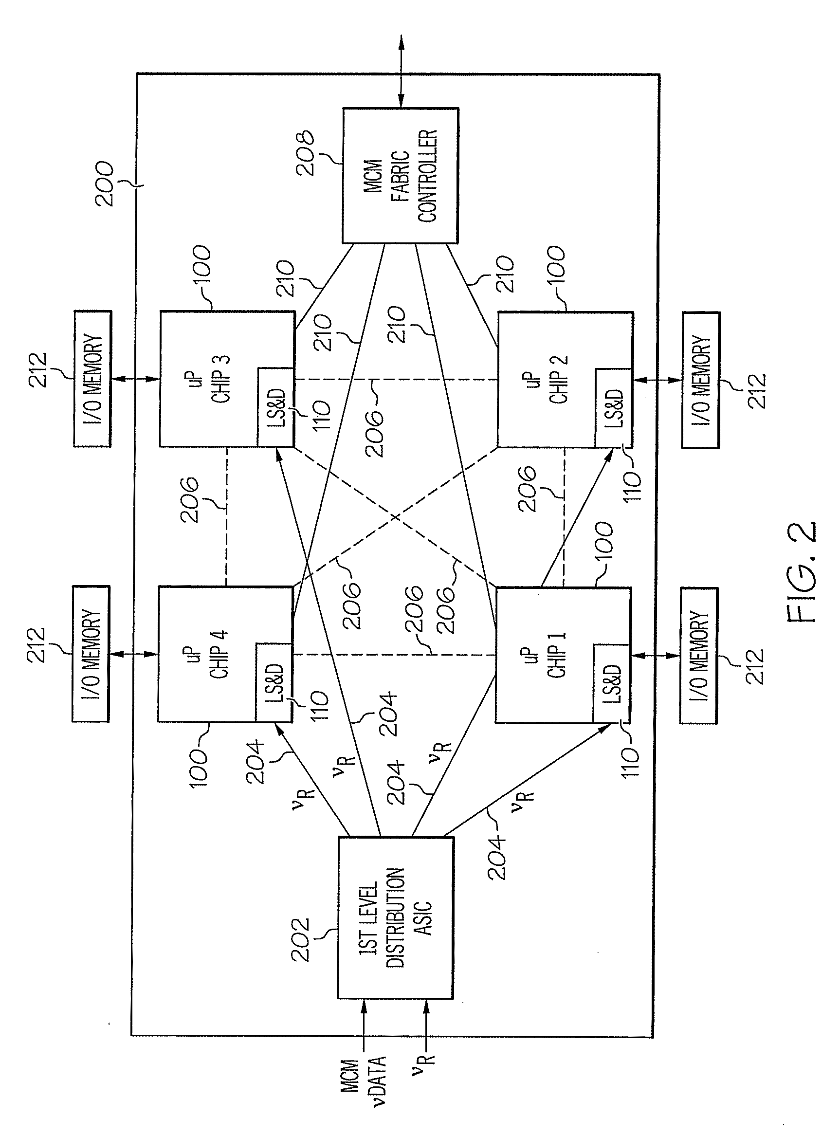
[0019]Exemplary embodiments provide methods and systems for digital multi-frequency clocking in multi-chip and / or multi-core processor systems. In exemplary embodiments, a computer system (e.g., a server) clocking subsystem with a single system reference oscillator provides both a reference clock for the computer system and a reference for individual processor cores but is not used directly to generate the individual core clocks. The system reference oscillator is used to provide a level of synchronization for the individual core clocks, which may be tightly synchronized or loosely synchronized based on the platform architecture. Exemplary embodiments allow for both tightly or loosely synchronized processors (e.g., based on local oscillator design) simultaneously within the same platform or a combination thereof, including degrees of asynchronous optimization.

[0020]Clock distribution to each processor chip and core may be achieved with a digital data signal via a distribution networ...


PUM


Abstract

A method and system for digitally controlled multi-frequency clocking are provided. The method includes receiving a system reference oscillator clock frequency at a microprocessor including multiple cores. The system reference oscillator clock frequency provides a reference frequency to a local oscillator. The local oscillator supplies a core clock frequency to at least one of the cores. The method further includes adjusting the local oscillator to output the core clock frequency at a frequency greater than the system reference oscillator clock frequency as a function of digital frequency characteristic data associated with the core or cores. The method supports extendibility to larger systems and may support enhanced power management through frequency adjustments at the core level.

Description

CROSS-REFERENCE TO RELATED APPLICATIONS[0001]This application contains subject matter related to the subject matter of the following co-pending application, which is hereby incorporated herein by reference in its entirety: U.S. patent application Attorney Docket No. POU920070208US1, entitled METHODS AND SYSTEMS FOR A DIGITAL FREQUENCY LOCKED LOOP FOR MULTI-FREQUENCY CLOCKING OF A MULTI-CORE PROCESSOR, filed on Oct. 17, 2007.BACKGROUND OF THE INVENTION[0002]The present disclosure relates generally to computer system clocking, and, in particular, to digitally controlled multi-frequency clocking of multi-core processors.[0003]Computer systems, such as servers, have encountered technology limitations associated with scaling performance by continuing to increase processor clock frequency. An approach being exploited in the industry to alleviate this bottleneck is the use of multiple processors working in synchronism to achieve higher performance. It has been shown that the scaling of the...

Claims


Application Information

Patent Timeline
Patent Type & Authority Applications(United States)
IPC IPC(8): G06F1/08
CPCG06F1/324Y02B60/1285Y02B60/1217G06F1/3296Y02D10/00
Inventor JACOBOWITZ, LAWRENCESTIGLIANI, JR., DANIEL J.
Owner IBM CORP
Why Eureka
Try Eureka