

Alignment method, imprint method, alignment apparatus, and position measurement method
- Summary
- Abstract
- Description
- Claims
- Application Information
AI Technical Summary
Benefits of technology
Problems solved by technology
Method used
Image

Examples
first embodiment
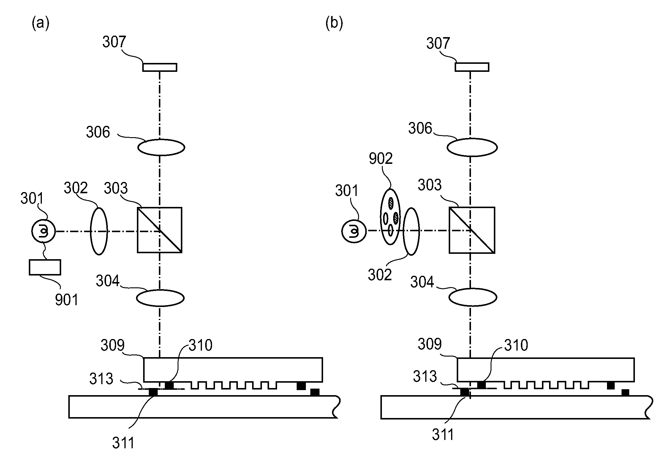
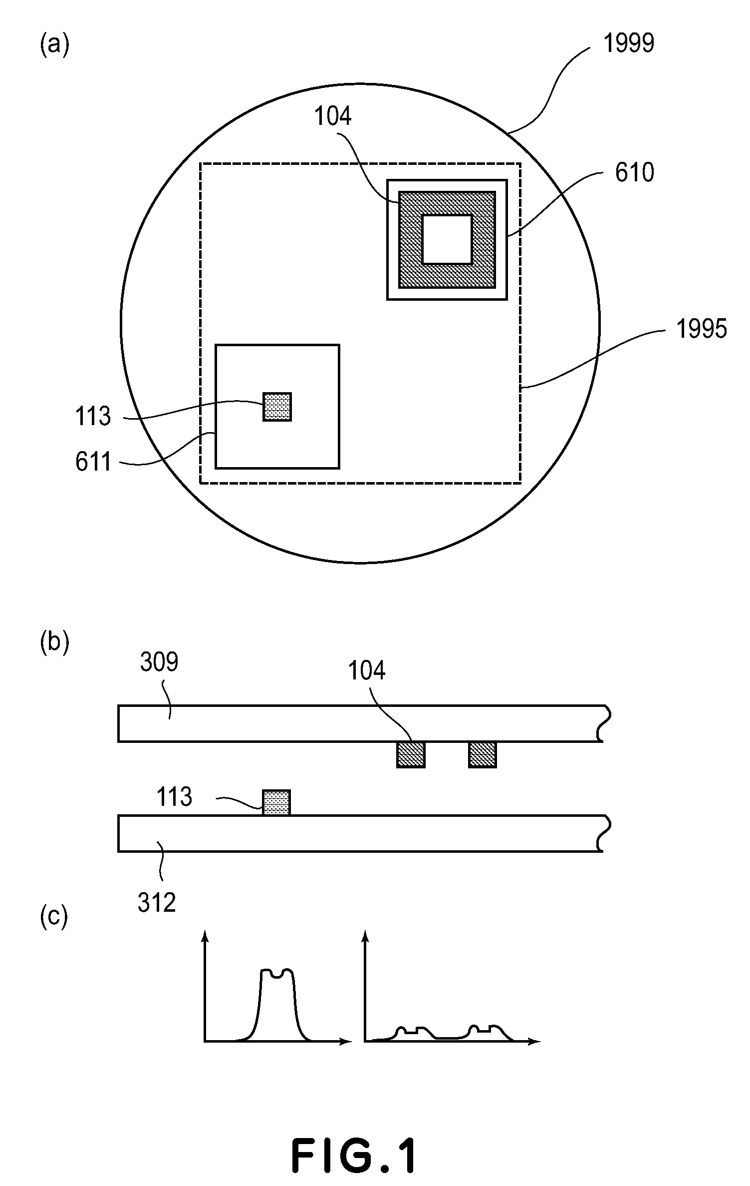
[0075]An alignment method according to the present invention for effecting alignment between two plate-like objects by using a light source and an image pickup device will be described with reference to FIGS. 1(a), 1(b) and 1(c).
[0076]FIG. 1(a) is a top view for illustrating an image of an image pickup area 1995 observed through an image pickup device located in a visible range 1999 in a body tube of a microscope. FIG. 1(b) is a sectional view for illustrating a state of the two plate-like objects disposed opposite to each other when these plate-like objects are viewed in a direction parallel to an in-plane direction thereof. FIG. 1(c) includes line profiles of marks which are specifically described later.
[0077]In the alignment method, first, a first plate-like object 309 provided with a first alignment mark 104 and a second plate-like object 312 provided with a second alignment mark 113 are disposed opposite to each other. In these cases, a first area 610 and a second area 611 are ...
second embodiment
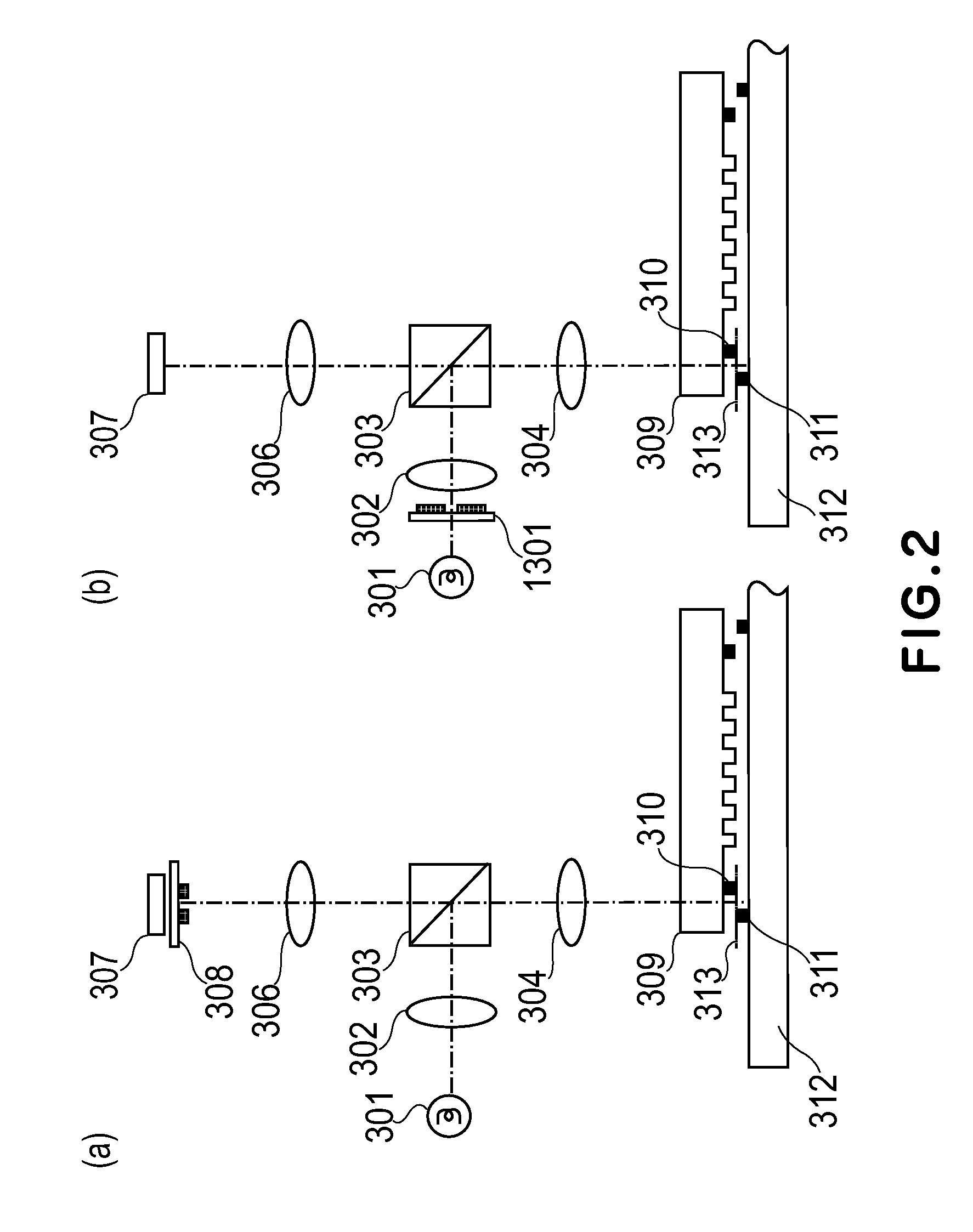
Imprint Method
[0113]An imprint method of Second Embodiment will be described.
[0114]In this embodiment, the alignment between the two plate-like objects is effected by using the image pickup device(s) similarly as in First Embodiment described above.
[0115]In this embodiment, imprint (transfer of an imprinting pattern) is performed so that an imprint pattern provided to one object is onto the other object or a pattern forming layer provided on the other object. In an actual operation, the imprinting pattern of a mold as one object is formed on the pattern forming layer as a reverse pattern thereof.
[0116]First, the mold as a first plate-like object having a first alignment mark and a substrate as a second plate-like object having a second alignment mark are disposed opposite to each other.
[0117]At a mutually nonoverlapping position in an image pickup area observed through an image pickup device, a first area and a second area are provided and then the first and second alignment marks a...
third embodiment
Electronic Generation of Moire Fringes
[0136]Third Embodiment of the present invention will be described.
[0137]More specifically, an alignment method of effecting alignment between two plate-like objects by using an image pickup device will be described.
[0138]First, a first plate-like object having a first periodic structure with a pitch P1 as an alignment mark and a second plate-like object having a second periodic structure with a pitch P2 as an alignment mark are disposed opposite to each other.
[0139]Then, similarly as in First Embodiment, a first area and a second area are provided at mutually nonoverlapping positions in an image pickup area to be observed through the image pickup device.
[0140]By using the image pickup device, images of the first and second periodic structures are picked up in the first and second areas, respectively, from a direction substantially perpendicular to an in-plane direction of the first and second plate-like objects.
[0141]From image information obtai...
PUM
| Property | Measurement | Unit |
|---|---|---|
| Length | aaaaa | aaaaa |
| Thickness | aaaaa | aaaaa |
| Area | aaaaa | aaaaa |
Abstract
Description
Claims
Application Information