
Method and device for displaying forecasts on a navigation plan

a navigation plan and forecast technology, applied in the field of aircraft flight plan displays, can solve the problem of not finding a future situation of the flight plan still displayed on the viewing screen, and achieve the effect of easy manipulation and quick decision-making

Active Publication Date: 2009-04-30
THALES SA
View PDF7 Cites 45 Cited by
  • Summary
  • Abstract
  • Description
  • Claims
  • Application Information

AI Technical Summary

Benefits of technology

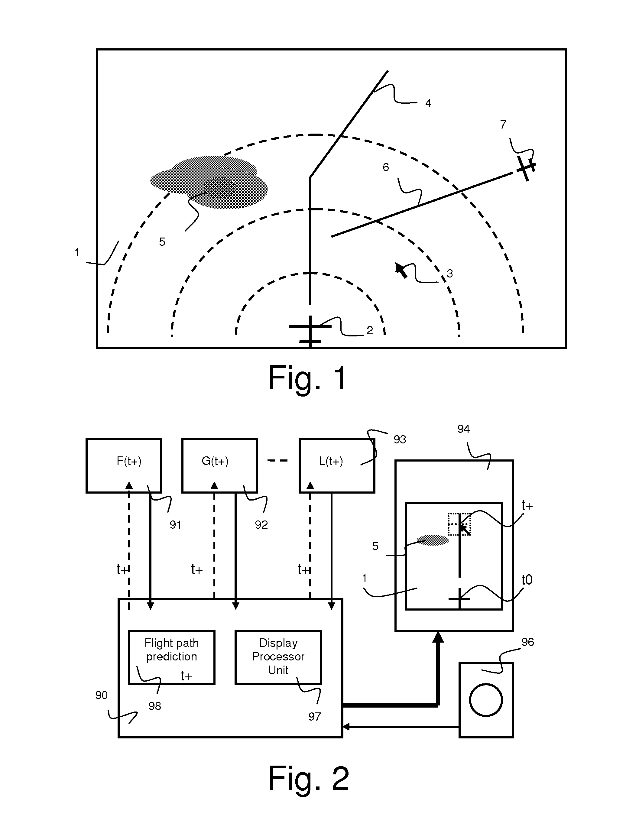
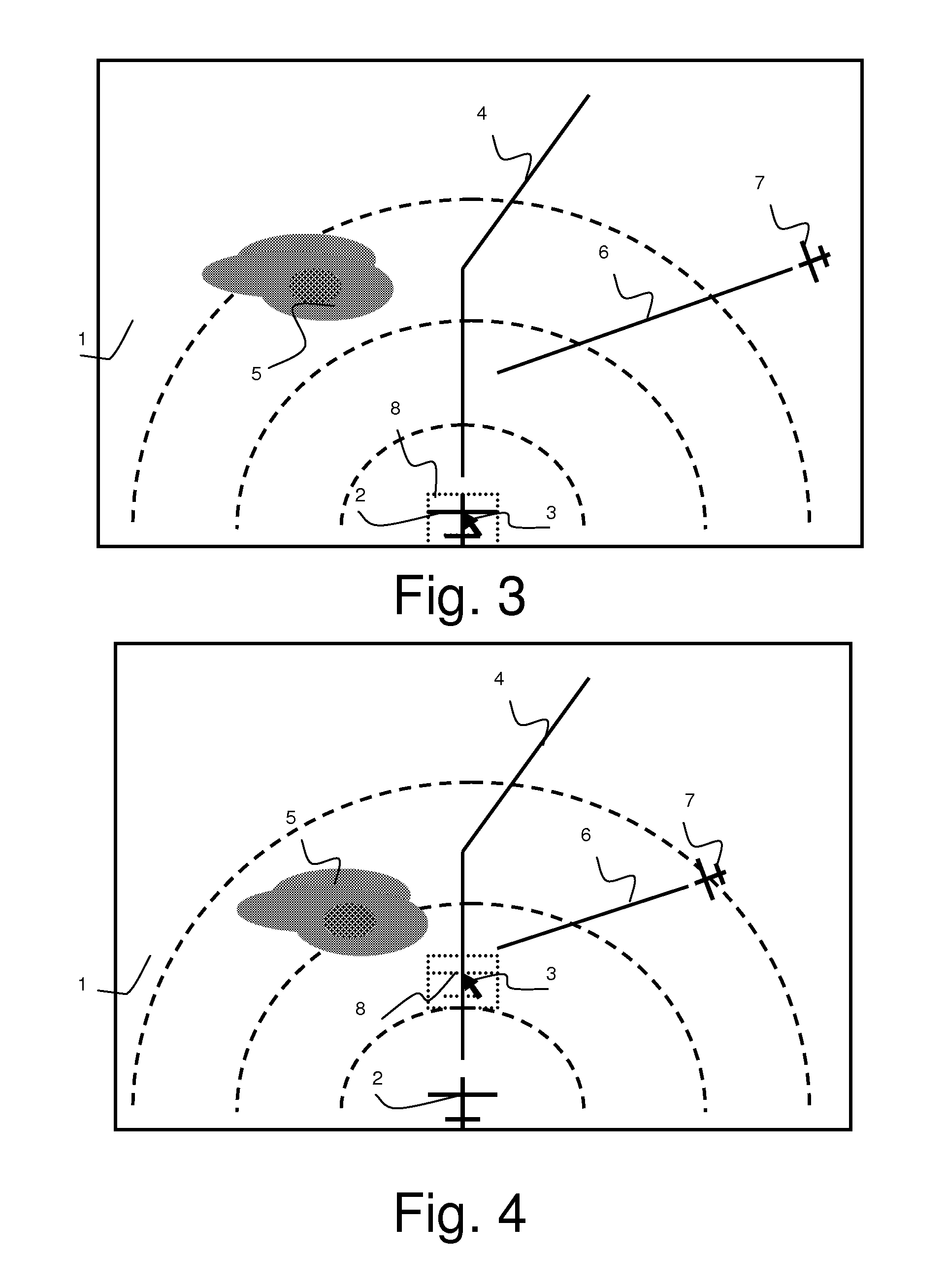
[0010]The invention is noteworthy in that the system uses the navigation plan as a temporal scale to display the forecast data originating from the various computers. Thus, the display of the forecasts is obtained by displacing a symbol along the planned route of the craft. This solution makes it possible to easily view the movement of the craft.
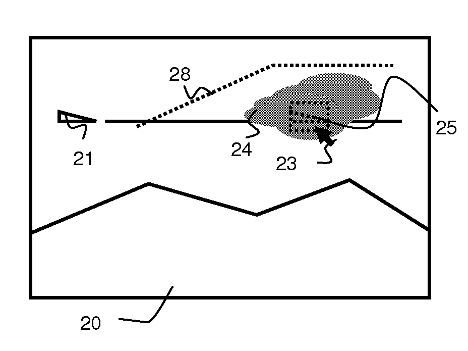
[0011]The cockpits now include pointing means intended for their viewing screens, of the same type as those commonly found in the computer domain. Advantageously, the selection is activated by an action on the pointing means and remains active as long as this action is maintained. Furthermore, it is necessary to make the user aware that the displayed data is forecast data. To avoid any interpretation error, the invention uses the “constrained human-machine interface (HMI)” concept. This means that, to view forecast data, the user is obliged to perform an action that makes him aware that he is viewing a future situation. Furthermore, immediately he stops this action, the system returns to the display of the current situation. Thus, when the pilot returns to this screen a little time later, he may not find a future situation of the flight plan still displayed on his viewing screen. Thanks to this method, interpretation errors due to the fact that the pilot might have forgotten that he asked the system to display a future situation are avoided.
[0012]Advantageously, the navigation plan and the first symbol are displayed permanently, this first symbol being fixed on the viewing screen. Furthermore, the position of the second symbol changes according to the navigation plan, this second symbol being displayed only when it is selected. In practice, it is necessary to display on the screen both symbols, the first fixed and the second moving on the flight plan plotted on the screen. The first symbol thus gives a temporal and spatial reference point and the moving second symbol on the flight plan makes it possible to view the changes to the situation from this reference. This method displaying the origin point with future information makes it possible to ensure that the user will correctly analyse the situation.
[0014]Advantageously, the display system can represent the navigation plan and the navigation data according to two perspectives: a top view and a lateral view. The pilot thus has visibility of the situation of the aeroplane in all four dimensions: the three spatial axes and the time dimension. In this way, the method provides an important aid to the decision to manoeuvre the aircraft. It is also possible to imagine using the method in a three-dimensional plan, a perspective closer to the situation seen by the pilot.
[0019]The invention can, if necessary, be applied to any craft comprising a navigation aid system such as ships or motor vehicles. More particularly, the invention will be applied to an aircraft comprising the device according to the invention implementing the method according to the invention. Advantageously, the means of calculating a navigation plan is a flight plan aid system. Since aircraft move at speeds far greater than other types of craft, the flight decisions need to be taken more rapidly and errors can have serious consequences. The invention makes it possible to facilitate the decision-making process thanks to a display method presenting the information clearly.
[0021]It is also possible, in a second embodiment, for one of the means of calculating future navigation data to be an aircraft flight path computer. In addition to the weather data, the pilot has the trend of the flight paths of the aeroplanes in the vicinity of his flight plan. In the case where he has to make a change of flight plan in order to avoid an area because of difficult weather conditions, he can easily view the position and the flight path of the other aeroplanes in the vicinity of the change-of-heading area. He thus has a clear vision of a future situation with the trend of the various surrounding parameters and can take good decisions quickly. In addition, manipulation is easy; the pilot simply has to select his aeroplane and move it on the flight plan by sliding the symbol using a cursor.

Problems solved by technology

Thus, when the pilot returns to this screen a little time later, he may not find a future situation of the flight plan still displayed on his viewing screen.

Method used


Image

  • Method and device for displaying forecasts on a navigation plan
  • Method and device for displaying forecasts on a navigation plan
  • Method and device for displaying forecasts on a navigation plan

Examples


Embodiment Construction

[0031]As a non-limiting example, the invention is applied according to FIG. 1 to the “navigation display”1 of an aeroplane. This display shows the flight plan 4 of the aeroplane 2. Today, these systems have a cursor 3 controlled by a pointing means 96, a function represented in FIG. 2. The display systems are generally associated with a graphic generation function 97 making it possible to present on the viewing screen 1 forecast data obtained from functions of forecasting computers 91, 92, 93. The invention can use any forecasting computer that would be used to display, on the navigation plan, weather forecasts, the state of the traffic, the terrain, the remaining fuel or communication frequency zones. In our example, it is a representation 5 of the weather forecasts obtained from the computer 91 handling a function F(t) taking as input parameter a date t+ generated by the flight plan computer 98, t+ being the date of the future position of the aeroplane 2 on the navigation plan 4. ...


PUM


Abstract

The invention applies particularly to the method and device for displaying forecasts on the flight plan of an aircraft. The method according to the invention consists in representing the craft by a first symbol in its current position and by a second symbol in its future position, in modifying the position of the second symbol on the navigation plan in order to change it to a future position, in displaying on the viewing screen the first symbol and at the same time the second symbol representing the craft on the navigation plan in a future position and in displaying on the viewing screen the navigation data at the instant of the future position of the craft.

Description

RELATED APPLICATIONS[0001]The present application is based on, and claims priority from, French Application Number 0707560, filed Oct. 26, 2007, the disclosure of which is hereby incorporated by reference herein in its entirety.BACKGROUND OF THE INVENTION[0002]1. Field of the Invention[0003]The field of the invention is that of aircraft flight plan displays or air traffic control station displays. It more generally concerns the devices and methods for displaying navigation plans for all types of craft (airborne, seaborne, terrestrial and spaceborne).[0004]2. Description of the Related Art[0005]It will be recalled that an aircraft is equipped with a navigation aid system called FMS, an acronym that stands for Flight Management System. The latter communicates with other external systems and systems on board the aircraft. The navigating crew communicates with the FMS via human-machine interfaces (HMI) having viewing screens and means of controlling and pointing to elements displayed on...

Claims


Application Information

Patent Timeline
IPC IPC(8): G01C21/20G06F19/00
CPCG01C23/00G08G5/0091G08G5/0078G08G5/0021
Inventor PINHEIRO, JEAN-PHILIPPE
Owner THALES SA
Learn More