Global navigation satellite system receiver and method of operation

Inactive Publication Date: 2009-04-30
SAMSUNG ELECTRONICS CO LTD
15 Cites 19 Cited by

AI-Extracted Technical Summary

Problems solved by technology

While this is not a problem for devices such as in-car navigation systems incorporating GPS receivers, where power consumption is not a consideration, it does pose a problem (in other w...

Method used

[0042]It will be appreciated that the power saving ability in certain embodiments of the invention is derived from the fact that the receiver utilizes software which is able to reduce the power consumption of the GPS RF front end by shutting down the receiver part of the device during reception of certain portions of data (data which is not required to be read, or extracted, in order to calculate a revised position). Other parts of the receiver device, such as clocks, may remain powered and running in order to provide timing signals and so enable the switching on of the receiver at the appropriate time.
[0044]The receiver 310 is such that it processes the received RF signals and outputs a corresponding digital signal to the base band processor 320 which can then be processed by the base band processor 320 to extract the data from the separate navigation messages of the navigation signals received together at the antenna 312. In general terms, the base band processor 320 is program...

Benefits of technology

[0018]Embodiments of the present invention therefore provide a receiver and a method of operating a receiver for a global navigation satellite system that overcomes one or more of the problems associated with the prior art. Particular embodiments aim to provide a method of operating a global navigation satellite system receiver which r...

Abstract

A system and method of operating a Global Navigation Satellite System (GNSS) receiver is disclosed, by receiving a plurality of navigation signals, operating the receiver in a first mode and operating the receiver in a second mode, each of the first navigation signals is a signal transmitted from a respective space vehicle and includes a respective sequence of navigation messages, each navigation message includes data indicative of at least a position of the respective space vehicle.

Application Domain

Navigational calculation instrumentsBeacon systems using radio waves +1

Technology Topic

Space vehicleSpacecraft +2

Image

  • Global navigation satellite system receiver and method of operation
  • Global navigation satellite system receiver and method of operation
  • Global navigation satellite system receiver and method of operation

Examples

  • Experimental program(1)

Example

[0028]Hereinafter, exemplary embodiments of the present invention will be described with reference to the accompanying drawings. In the following description, the same elements will be designated by the same reference numerals although they are shown in different drawings. Further, in the following description of the present invention, a detailed description of known functions and configurations incorporated herein will be omitted when it may make the subject matter of the present invention rather unclear.
[0029]The following description of particular embodiments of the invention will concentrate particularly on GPS receivers and their operation. However, it will be appreciated that the present invention is not limited to GPS systems, and alternative embodiments provide receivers and methods of operation for other GNSSs.
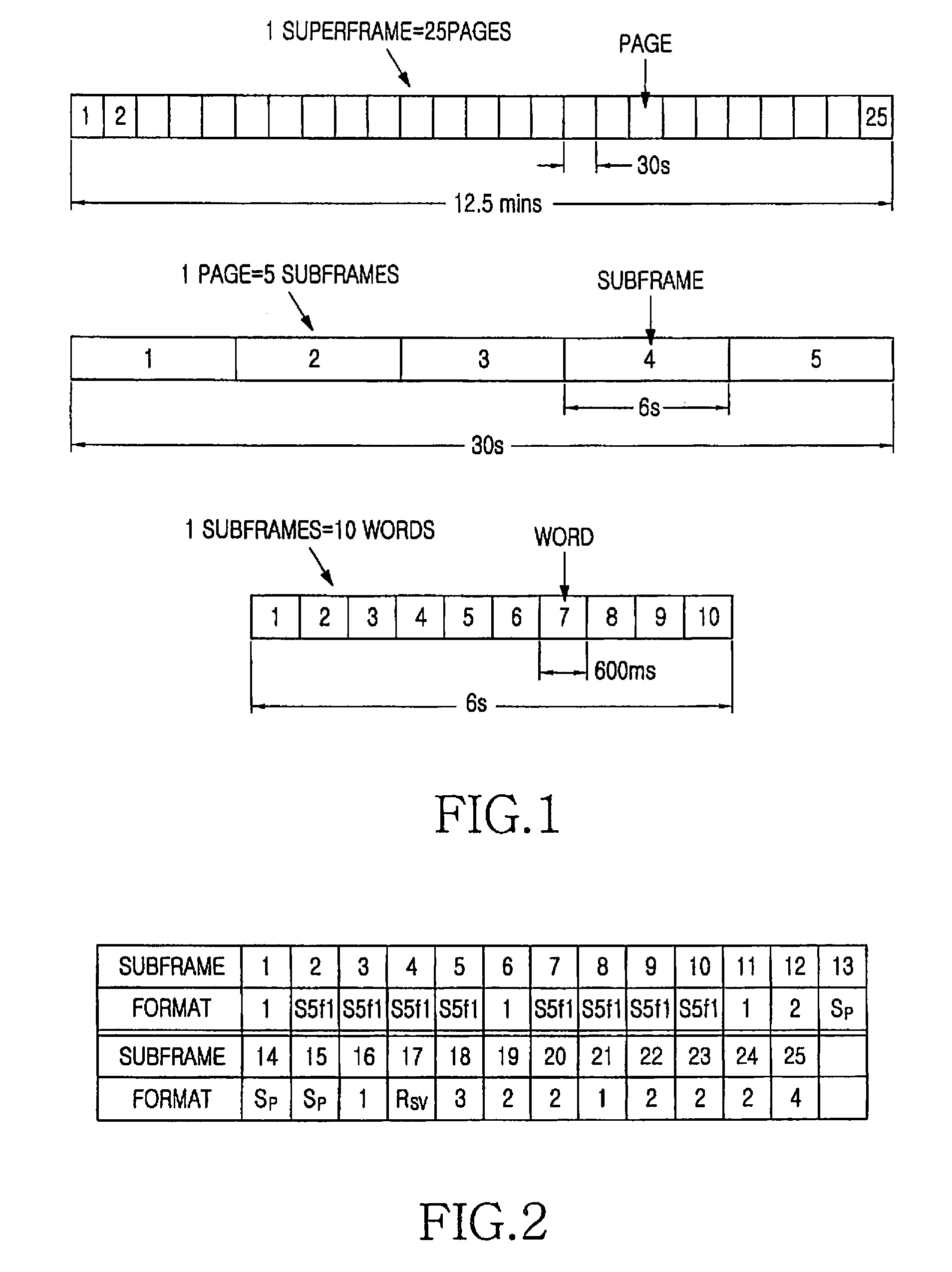
[0030]A conventional GPS receiver decodes 25 pages (known collectively as a superframe), each comprising 5 subframes of 300 bits each subframe, over a 12.5 minute period. In traditional implementations, the complete superframe is read during both acquisition and tracking modes, thus requiring that the GPS RF receiver and associated GPS baseband processing be active for the entire duration of the operation. In other words, conventional GPS receivers are arranged to extract all data from each navigation message from each of typically four SVs during acquisition and subsequent tracking modes. The superframe/subframe/word structure of a typical GPS navigation message is illustrated in FIG. 1.
[0031]FIG. 1 is a diagram illustrating the structure of a navigation message in the GPS format. Referring to FIG. 1, Subframes 1, 2 and 3 occur at the start of every page, with subframes 4 and 5 being subcommutated over the entire 25 pages of the superframe. Subframe 5 has two formats; format 1 is used for all the pages, apart from the final page (page 25), where format 2 is used. Subframe 4 is considerably more complex, having 6 different formats, and also using format 1 of subframe 5. In addition, the format of subframe 4 does not repeat in a periodic fashion within the superframe, but is mapped into it as shown in FIG. 2.
[0032]FIG. 2 is a diagram illustrating the variation of the format of subframe 4 of a GPS navigation message as a function of the page number throughout the 25 pages of a single navigation message. Referring to FIG. 2, certain embodiments of the invention utilize the fact that there is a degree of repetition of data within the superframe of a GPS navigation message (and others). For example, in certain embodiments the previous requirement to read all of the pages is removed.
[0033]In certain embodiments of the invention, once the signal from each SV has been acquired (and position has been determined (i.e. calculated) to within a predetermined accuracy), the reading frequency of the fine ephemeris data contained in subframes 1, 2 and 3 is reduced to a lower rate. This can be achieved by omitting certain subframes (i.e. not extracting data from those subframes). During the time of the omitted subframes, a GPS RF front-end of the receiver is put into a low-power mode, and woken up for the occurrence of the next required subftame. The time to wake-up from low-power mode in order to read the next required subframe can be determined from the timing information previously decoded from the navigation stream (i.e. the plurality of received navigation messages).
[0034]In the case where the navigation stream being read deteriorates to an unacceptable level such that decoding cannot be acceptably performed (position cannot be determined with sufficient accuracy, if at all) then the receiver, for example by operating according to a predetermined or pre-programmed algorithm, in certain embodiments is arranged to revert to its “first”, or normal power consumption mode of operation, in which the receiver attempts to extract all data from the incoming navigation messages, and begins to immediately read the next occurrence of subframes 1, 2 and 3 until new data is received and extracted which enables the normal decoding level required for navigation. Once this is achieved, operation in the second (reduced-power) mode (with subframe reading at reduced frequency) is re-established.
[0035]Control algorithms employed in certain embodiments of the invention include knowledge of the superframe structure in order to know when the GPS RF front-end can be safely put to “sleep” (i.e. into a low power mode of operation, or off altogether) without missing essential information elements. This is especially true for the monitoring of subframe 4, as the subframe reserved in page 17 for special messages and the format 3 subframe in page 18 only occur once per superframe.
[0036]Certain embodiments of the invention use of the following techniques to choose which subframes, or portions thereof, within each page to decode: a sliding window technique and a “sub-frame hopping” pattern.
[0037]The sliding window scheme may employ a sampling window across the periodic superframe, where the size of the window used is a modulo-1 factor of the entire superframe. This ensures that over time every message is read. A careful choosing of the window size can ensure that subframes that only occur once per superframe are never missed in the reading schedule.
[0038]The concept behind the “sub-frame hopping” technique is similar to that behind frequency-hopping in conventional radio communications, in which a hopping pattern is used which determines the next frequency to be used and is seeded from an initial point, usually a fixed time period. In certain embodiments of the invention, a hopping pattern is used which selects navigational data elements from each subframe. In this way, the validity period of each data element can be used to schedule the next time to read, by marking it appropriately in the hopping plan.
[0039]As can be seen from the complete 25-frame superframe, there is much spatially redundant information in the message, but its temporal position may be important, depending on the position of the SV. Use of the hopping technique ensures that any data missed may be accurately reconstructed by using the remaining navigation data that was last read.
[0040]The most important parts to be hopped (i.e. selectively ignored or not extracted) in certain embodiments are the almanac data contained in subframes 4 and 5, as that data is valid for a period of several weeks. Subframe 1 is read every time in certain embodiments (i.e. its data is extracted from each page of each navigation message), as it contains rapidly changing and vitally important parameters, such as clock correction.
[0041]A second-order polynomial may be used to implement the sliding-window technique in certain embodiments, while still allowing coverage of the unique blocks in subframe 4.
[0042]It will be appreciated that the power saving ability in certain embodiments of the invention is derived from the fact that the receiver utilizes software which is able to reduce the power consumption of the GPS RF front end by shutting down the receiver part of the device during reception of certain portions of data (data which is not required to be read, or extracted, in order to calculate a revised position). Other parts of the receiver device, such as clocks, may remain powered and running in order to provide timing signals and so enable the switching on of the receiver at the appropriate time.
[0043]FIG. 3 is a schematic diagram of a GPS receiver embodying the invention. Referring to FIG. 3, the GPS receiver generally includes receiver 310 and base band processor or digital signal processor (DSP) 320, antenna 312, RF processor 314, controller 315, base band clock generator 316 and reference clock generator 318. The antenna 312 is arranged to receive radio frequency (RF) navigation signals from a plurality of satellites in the GPS constellation. The received RF signals are initially processed by the RF processor 314 (which may also be referred to as an RF front end, or RF processing stage). The reference clock generator 318 provides a reference clock signal to the RF front end 314, the base band clock generator 316 connected to the RF front end 314, the reference clock, and the controller 315, and adapted to provide a GPS base band clock signal 330 to the base band processor 320. The controller 315 is arranged to receive control signals via a control connection in the form of a GPS control bus 330 from the base band processor 320.
[0044]The receiver 310 is such that it processes the received RF signals and outputs a corresponding digital signal to the base band processor 320 which can then be processed by the base band processor 320 to extract the data from the separate navigation messages of the navigation signals received together at the antenna 312. In general terms, the base band processor 320 is programmed in accordance with knowledge of the format of GPS navigation messages and, once signals from a sufficient number of satellites have been acquired and the base band processor has determined the position of the receiver to a sufficient accuracy, the base band processor 320 is then able (by supplying appropriate control signals via the GPS control bus 330) to switch off or power down a selected portion or portions of the receiver 310 and so reduce power consumption while certain portions of incoming navigation messages are being received. In other words, the base band processor 320 has been programmed in such a way that it takes into account an inherent redundancy in the data structure of incoming navigation messages and also takes into account the position of the unused portions of the navigation message such that when certain portions of navigation messages are being received, data need not be extracted from them, and power consumption during these periods can thus be reduced.
[0045]A GPS superframe contains a large amount of bits in its structure that are at present unused, that is, they are reserved for future purposes, and bits that contain repeated informational elements. With regard to “unused” bits, certain embodiments of the invention are programmed with knowledge of the navigation message structure and hence the positions of these unused bits. The receivers are then adapted to synchronize with the received signals and then control the GPS RF front-end to operate in a low power mode during the time these “unused” bits are being transmitted. The receiver is then arranged to return the RF front-end to normal operation just before this period ends. In certain embodiments this “powering-down” of the RF front end includes switching off one or more parts (devices, circuits, stages, components etc.). Because parts of the GPS RF front-end are switched off in certain examples, there is a small amount of time required to return these parts of the device to their fully functional state. This is dealt with by re-activating those parts of the device a predetermined time interval (e.g. 20 milliseconds) before the data stream is required to be read again. This timing of switch-off and switch-on in relation to a portion of a navigation message to be “ignored” is shown in FIG. 4.
[0046]FIG. 4 is a representation of part of a navigation message illustrating the relationship between data in the message and a period of time selected by the control means of the receiver. Referring to FIG. 4, this shows a portion 400 of a navigation message which comprises data. During receipt of a first portion of data 402 the RF front end 314 the GPS receiver is controlled so as to be in a fully on state, such that all of that data 402 is extracted. Then, based on the knowledge of the incoming navigation message, and having already been synchronized with the incoming message, the base band processor 320 controls the RF front end to switch off at a time T1404. The base band processor 320 has determined that a second portion of data 406 is unwanted (and is not needed to calculate an updated position of the receiver). The base band processor 320 is then arranged to return the RF front end 314 to its fully “on” state at a time T2408, which in this example is 20 milliseconds before a time T3410 which corresponds to the beginning of the next portion of data 402 to be read (i.e. processed, and its data extracted).
[0047]Clearly, the details of which portions of data may be ‘ignored’ in embodiments of the invention depends on the particular format of the incoming navigation messages, and hence base band processor 320 in receivers embodying invention should be programmed in accordance with knowledge of the format of the navigation messages of the particular system in which the receiver is to be used. With regard to GPS receivers, embodiments of the invention may be arranged to selectively omit one or more of the following areas of a GPS superframe, as at present they do not contain any useful navigation data.
TABLE 1 Subframe 1 word bits 3 11-12 4 1-24 5 1-24 6 1-24 7 1-16
TABLE 2 Subframe 2 word bits 10 17-22
TABLE 3 pages 1, 6, 11, 12, 16, 19, 20, 21, 22, 23 and 24 bits 69-300
[0048]Because the 6 parity bits per subframe only relate to that particular subframe, if all 24 preceding bits of a subframe are skipped, then the associated 6 bit parity field may also be omitted. However, if only part of the preceding 24 bits are skipped, then the parity part should be ignored, although this has the potential for corrupt navigation to be used, although analysis of where data is omitted in the frame cycle shows that the likelihood of this happening is extremely small.
[0049]With regard to potential power saving with embodiments of the invention, the following calculations are based upon skipping non-essential data from subframes 1 and subframe 4, format 1.
(90 bits skipped in subframe 1)+(232 bits skipped in subframe 4 format 1)=322 bits per page ((322 bits×25 pages)/37500 bits per superframe)×100=21.46%
[0050]Therefore this basic implementation would give a battery power saving of over 20%.
[0051]FIG. 5 is a schematic representation of some of the components of a GPS receiver in accordance with another embodiment of the invention. Referring to FIG. 5, the GPS receiver 500 includes antenna 502, impedance matching circuit 504, Low Noise Amplifier (LNA) 506, RF Band Pass Filter (BPF) 508, RF mixer 510, Phase Locked Loop (PLL) frequency synthesiser circuit 512, Variable Gain Amplifier (VGA) 514, Low Pass (LP) filter 516, and Analog to Digital Converter (ADC) 518.
[0052]The antenna 502 is connected to impedance matching circuit 504. Via this impedance matching circuit 504, the antenna 502 passes the combination of received navigation RF signals to LNA 506. The amplified signal from LNA 506 is then filtered by RF BPF 508, and the filtered signal is provided to RF mixer 510. The RF mixer 510 is arranged to received a Local Oscillator (LO) signal from PLL frequency synthesiser circuit 512 which synthesizes the LO oscillating signal from an accurate reference clock signal from a reference clock generator 524. The output from the RF mixer 510 is essentially a carrier-stripped signal. Although it should be kept in mind that this signal still includes a mixture of incoming navigation messages, as in this embodiment those signals are processed initially in parallel; this is possible because the different satellites of the GPS system have modulated the carrier signals using CDMA techniques. The carrier-stripped signal is then amplified by VGA 514 and the amplified signal is then filtered by LP filter 516 before being supplied to ADC 518. ADC 518 is arranged to sample the signal from the LPF 516 at a sampling rate which is sufficiently high to preserve essentially all of the data from all of the component navigation messages. In other words, the GPS digital data 520 output from the ADC 518 does not simply correspond to a single one of the incoming navigation messages, instead it includes data from a plurality of incoming messages and the data from the individual messages can then be extracted by appropriate subsequent processing (e.g. using correlation techniques). This subsequent processing is performed by a processor or DSP which is part of the receiver, not shown in FIG. 5.
[0053]The GPS receiver 500 also includes a GPS clock generator 522, which receives the reference clock signal from the reference clock generator 524. The GPS clock generator 522 provides a GPS clock signal 526 to the ADC 518 and also outputs the signal (for example for use by the DSP). The receiver 500 also includes a battery 528 which supplies the power to operate the various receiver components. The battery 528 supplies this power via a GPS voltage regulation circuit 530, which itself is arranged to be controlled by control signal 1332 (GPS_EN) from a suitable control means (e.g. the DSP).
[0054]In use, and after the GPS receiver 500 has acquired the satellite navigation signals and has determined its position, the control means of the receiver is arranged to control the GPS receiver 500 to operate in a power save mode during receipt of certain portions of the incoming navigation messages. In power save mode, the LNA 506, the RF mixer 510, the PLL frequency synthesizer 512, the VGA amplifier 514, and the ADC 518 are switched off (by means of a control signal 2534 from the GPS receiver's control means (the control means is not illustrated in FIG. 5).
[0055]This control signal 2534 may, for example, be a signal on a GPS_RX_EN control line, or may be a control signal supplied via a control bus such as the 3 wire bus 536. Although the above mentioned components, stages or circuits are switched off in the power save mode, the GPS voltage regulator 530, the reference clock 524 and the GPS clock generator 522 are arranged to remain on in this embodiment for fast recovery, in other words, to enable the signal processing means of the receiver to rapidly resume proper operation at the end of the period of operation in power save mode.
[0056]Referring now to FIGS. 6A, 6B and 6C, these show three sequences: sequence 1600, sequence 2610, and sequence 3620, each of navigation message 1, 2 and 3. Each sequence includes three separate navigation messages shown respectively in FIGS. 6A, 6B, and 6C. The messages and selected data portions thereof are shown in schematic and simplified form but generally indicate different time period selections employed in different embodiments of the invention. For sequence 1600 the control means of the receiver has been arranged to ‘ignore’ the same portions of unwanted data E in each of the three messages shown in FIGS. 6A, 6B and 6C. In other words, the control means of the receiver has been arranged to switch off or at least power down at least one of the active signal processing means so that the same pieces of data in each of the three messages shown in FIGS. 6A, 6B and 6C is ignored (i.e. is not extracted).
[0057]Sequence 2610 shows an alternative technique in which the control means of the receiver has selected different portions E of data to ignore in each of the sequence of three messages. Thus, the positions of the data being extracted, and the positions of the data not being extracted (i.e. being ignored) vary from message to message.
[0058]In sequence 3620 the receiver has been arranged to implement a ‘sliding window’ technique of data extraction in which the position of the portion of data E not being extracted changes from one message to the next in a predetermined manner.
[0059]It will be appreciated that a receiver as shown in FIG. 5 may also be used to implement a method as defined in the claims. To do so, the control means need not power down the various front end components during tracking mode (although it could do so, to save even more power), but the DSP is arranged to perform a reduced quantity of processing in the second, tracking mode to arrive at an updated position. It will also be appreciated that, while calculating updated position using a reduced number of processing operations, the DSP in certain embodiments may use the “saved” processing capacity for some other processing function.
[0060]While the invention has been shown and described with reference to certain exemplary embodiments thereof, it will be understood by those skilled in the art that various changes in form and details may be made therein without departing from the spirit and scope of the invention as defined by the appended claims.

PUM

no PUM

Description & Claims & Application Information

We can also present the details of the Description, Claims and Application information to help users get a comprehensive understanding of the technical details of the patent, such as background art, summary of invention, brief description of drawings, description of embodiments, and other original content. On the other hand, users can also determine the specific scope of protection of the technology through the list of claims; as well as understand the changes in the life cycle of the technology with the presentation of the patent timeline. Login to view more.

Similar technology patents

Efficient route update protocol for wireless sensor network

InactiveUS20050157698A1minimize power consumption differencereduce power consumption
Owner:SAMSUNG ELECTRONICS CO LTD +1

Demand response method, computer-readable medium and system

ActiveUS20110208369A1reduce power consumptionreduced power rate
Owner:SAMSUNG ELECTRONICS CO LTD

Classification and recommendation of technical efficacy words

  • reduce power consumption
  • prolong battery life

Electrode array for use in medical stimulation and methods thereof

InactiveUS20050038489A1reduce power consumptionincrease battery life
Owner:CASE WESTERN RESERVE UNIV

Method of reselecting a cell based on priorities

ActiveUS20090181676A1ensure quality of servicereduce power consumption
Owner:LG ELECTRONICS INC

Organic light-emitting devices with mixed electron transport materials

InactiveUS20060204784A1good luminance efficiency and stabilityreduce power consumption
Owner:EASTMAN KODAK CO

Low-complexity depth map encoder with quad-tree partitioned compressed sensing

InactiveUS20160050440A1low computational costprolong battery life
Owner:ILLINOIS INSTITUTE OF TECHNOLOGY

System and method of continuous health monitoring

InactiveUS20190082968A1minimize latencyprolong battery life
Owner:KARNIK PRASAD +1

System and method for providing a low power remote control

ActiveUS20120066528A1prolong battery lifereduce energy consumption
Owner:UNIVERSAL ELECTRONICS INC

Circuit and method for providing an auto-off capability for a wireless transmitter

InactiveUS20080214122A1prolong battery lifeeliminate transmission
Owner:AERIELLE TECH

Fish Strike Indicator

InactiveUS20170099824A1prolong battery life
Owner:MANASCO SR ROY ORLAND
Why Eureka
Try Eureka