
In-Liquid Plasma Electrode, In-Liquid Plasma Generating Apparatus and In-Liquid Plasma Generating Method

a plasma electrode and liquid technology, applied in the field of plasma technology for generating plasma in liquid, can solve the problems of electromagnetic wave attenuation, electromagnetic wave generation, electromagnetic wave generation, etc., and achieve the effect of high energy in-liquid plasma

Inactive Publication Date: 2009-04-30
TOYOTA IND CORP +1
View PDF11 Cites 21 Cited by
  • Summary
  • Abstract
  • Description
  • Claims
  • Application Information

AI Technical Summary

Benefits of technology

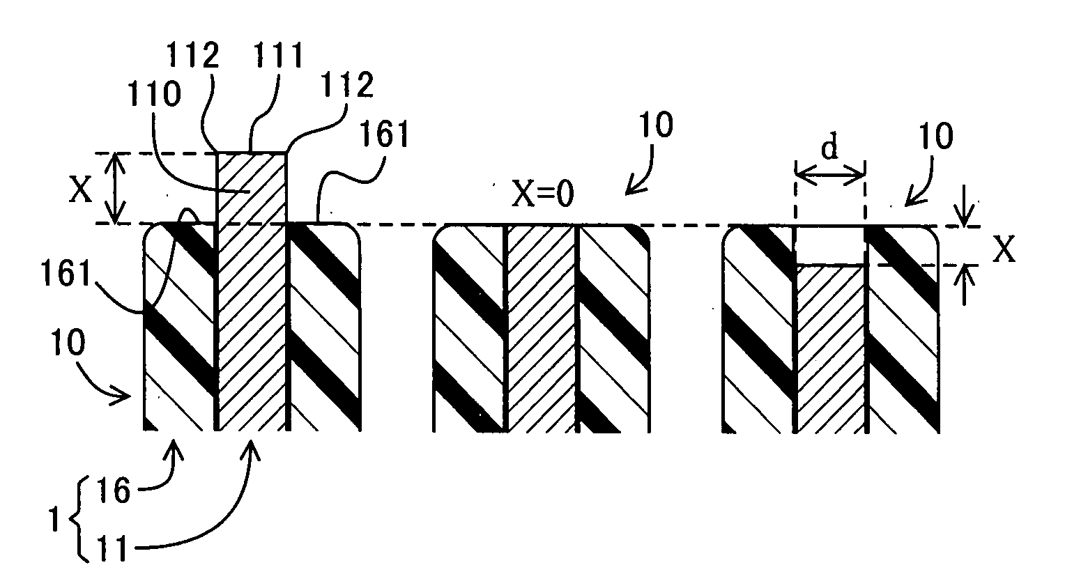
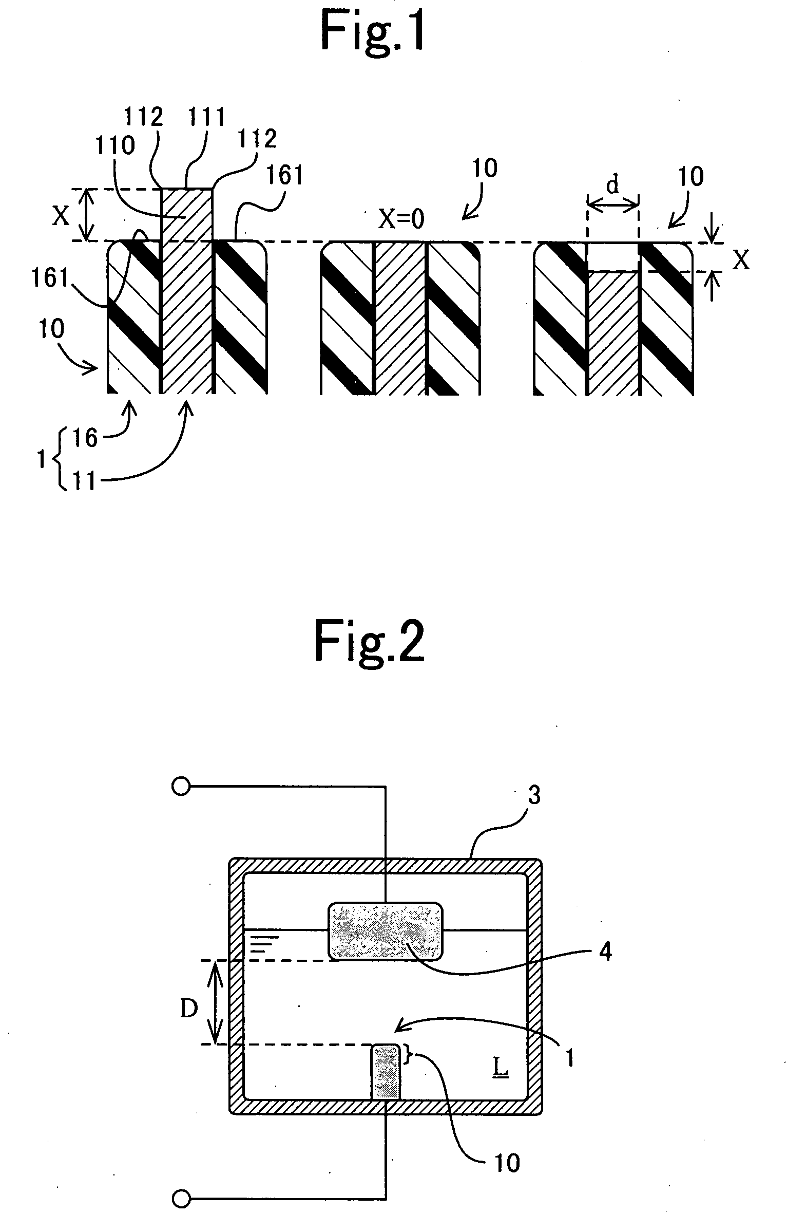
[0012]According to the in-liquid plasma electrode of the present invention, since an insulating member is provided at an outer periphery of the conductive member at least except the electric discharge end surface, an advantage of being capable of generating high energy plasma in a wide variety of liquids such as a water-containing liquid is obtained. Moreover, since the relationship between the abovementioned d and the abovementioned x is maintained in an appropriate range, plasma can be generated in a liquid without applying extremely large electric power to the electrode. Therefore, a large electric power source is not necessarily required. Furthermore, the in-liquid plasma electrode has a simple structure and an in-liquid plasma generating apparatus mentioned later can be made simple.
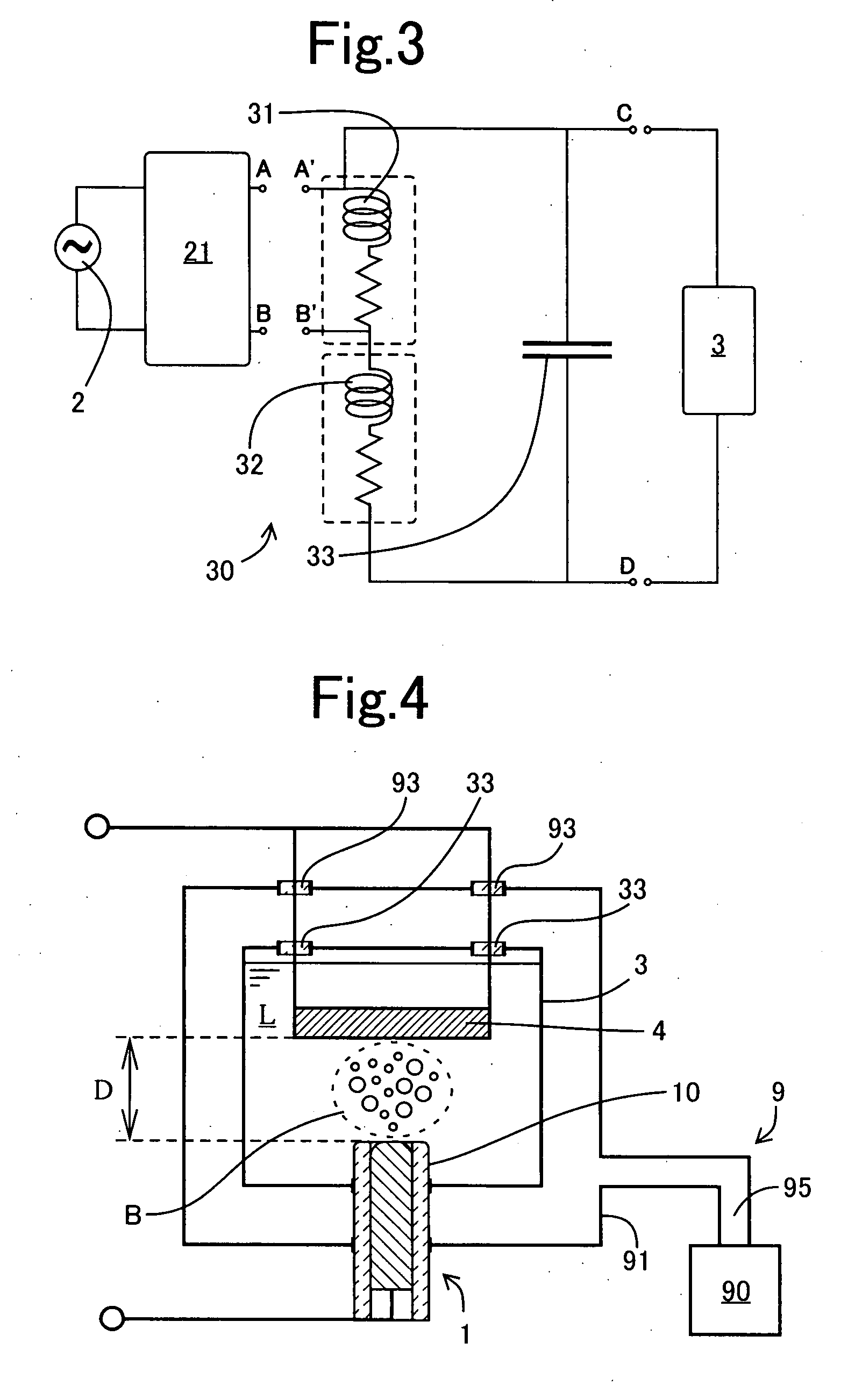
[0018]Owing to the abovementioned in-liquid plasma electrode of the present invention, the in-liquid plasma generating apparatus and the in-liquid plasma generating method of the present invention have an advantage of being capable of generating high energy in-liquid plasma in a wide variety of liquids such as a water-containing liquid.

Problems solved by technology

However, in a conductive liquid such as water and alcohol, there is a problem that eddy current is generated in the liquid and dissipates energy of the radiated electromagnetic waves.
There is also a problem that the electromagnetic waves attenuate because a hydroxyl group or the like absorbs a certain frequency.

Method used


Image

  • In-Liquid Plasma Electrode, In-Liquid Plasma Generating Apparatus and In-Liquid Plasma Generating Method
  • In-Liquid Plasma Electrode, In-Liquid Plasma Generating Apparatus and In-Liquid Plasma Generating Method
  • In-Liquid Plasma Electrode, In-Liquid Plasma Generating Apparatus and In-Liquid Plasma Generating Method

Examples


first embodiment

[0058]An in-liquid plasma electrode 1′ comprises a conductive member 12 formed of metal and an insulating member 17. FIG. 5 is an axially cross sectional view of an electrode end portion 10′ of one example of in-liquid plasma electrodes 1′ of a first to fifth embodiments. Employed as the conductive member 12 was a cylindrical column (diameter: 3 mm (d=3)) formed of pure aluminum (A1050 (JIS)) and having a flat end surface 121 on one end. In this embodiment, this end surface 121 was used as the electric discharge end surface. At an edge of the end surface 121, a chamfered portion 122 of R=0.2 mm was formed. In addition, employed as the insulating member 17 was a cylindrical ceramic insulating tube (inner diameter: 3 mm, outer diameter: 5 mm, length: 25 mm). The conductive member 12 was inserted into the tubular insulating member 17. At the electrode end portion 10′ of the in-liquid plasma electrode 1′, the insert position of the conductive member 12 was adjusted to determine a distan...

second embodiment

[0063]In a second embodiment, as an example of a liquid containing a hydroxyl group, alcohol was used as the liquid L. Namely, plasma was generated by the in-liquid plasma generating apparatus in a similar way to the first embodiment, except that the liquid L was ethanol and the in-vessel pressure was set at 100 hPa. The in-liquid plasma electrodes 1′ used at this time were respectively assembled to the vessel 3 in such a manner that x=1, x=0, and x=−1. Regarding the respective electrodes, values of the high frequency electric power when an electric discharge occurred are shown in Table 2.

TABLE 2CONDUCTIVE MEMBERSIZEDISTANCEKIND OFINTERELECTRODEIN-VESSELELECTRIC POWER ATELECTRODEMATERIALd [mm]x [mm]LIQUIDSDISTANCE D [mm]PRESSURE [hPa]PLASMA GENERATION [W]#2-1Al (A1050)3+1ETHANOL2100100#2-2Al (A1050)30ETHANOL2100100#2-3Al (A1050)3−1ETHANOL2100100

[0064]Even when the liquid L was ethanol, plasma could be generated. In addition, even when the electric discharge end surface 121 protruded...

third embodiment

[0066]Plasma was generated by the in-liquid plasma generating apparatus in a similar way to the first embodiment, except that the conductive member 12 had a diameter of 1.5 mm (d=1.5), the liquid L was ethanol, the interelectrode distance D was 3mm, and the in-vessel pressure was 100 hPa. The inner diameter of the insulating member 17 was also changed to 1.5 mm so as to fit the diameter of the conductive member 12. The in-liquid plasma electrodes 1′ used at this time were respectively assembled to the vessel 3 in such a manner that x=±4, ±3, ±1, 0. Regarding the respective electrodes, values of the high frequency electric power when an electric discharge occurred are shown in Table 3.

TABLE 3CONDUCTIVE MEMBERSIZEDISTANCEKIND OFINTERELECTRODEIN-VESSELELECTRIC POWER ATELECTRODEMATERIALd [mm]x [mm]LIQUIDSDISTANCE D [mm]PRESSURE [hPa]PLASMA GENERATION [W]#3-1Al (A1050)1.5+4ETHANOL3100>600#3-2Al (A1050)1.5+3ETHANOL3100480#3-3Al (A1050)1.5+1ETHANOL3100200#3-4Al (A1050)1.50ETHANOL3100200#3-...


PUM


Abstract

An in-liquid plasma electrode 1 according to the present invention is an in-liquid plasma electrode for generating plasma in a liquid L and has a conductive member 11 having an electric discharge end surface 111 in contact with the liquid L, and an insulating member 16 covering an outer periphery of the conductive member 11 at least except the electric discharge end surface 111. Preferably, d and x satisfy −2d≦x≦2d, where d is a length of a minor axis of the cross section when a conductive end portion 110 of the conductive member 11 having the electric discharge end surface 11 has a roughly circular cross section, or d is a length of a short side of the cross section when the conductive end portion 110 has a roughly rectangular cross section, and x is a distance from a reference plane 161 to a plane containing the electric discharge end surface 111 when the reference plane 161 is an end surface 161 of the insulating member 16 in roughly parallel with the electric discharge end surface 111. Owing to this construction, it is possible to provide an in-liquid plasma electrode which can simply generate plasma in a wide variety of liquids including a conductive liquid such as water and alcohol, and furthermore an in-liquid plasma generating apparatus having this electrode, and an in-liquid plasma generating method using this electrode.

Description

TECHNICAL FIELD[0001]This invention relates to plasma technology for generating plasma in a liquid and more particularly to a method and an apparatus for generating high energy plasma in a liquid and an electrode used therein.TECHNICAL BACKGROUND[0002]As vapor deposition technique using plasma, vapor deposition technique using vapor phase plasma has conventionally been used widely. However, in vapor phase plasma, which has a low material density, the reaction rate is low. Therefore, there is a need for technology for generating plasma in a liquid, which has a high material density.[0003]For example, the pamphlet of International Publication No. 02 / 038827 (Document 1) describes an invention of producing a stream of bubbles containing a source of a material to be deposited in an electrolyte in which a pair of spaced electrodes are disposed and generating plasma glow discharge in the bubble region, thereby depositing the material on one of the electrodes.[0004]However, the invention re...

Claims


Application Information

Patent Timeline
IPC IPC(8): G09G3/28B01J19/08H05H1/24
CPCB01J19/088B01J2219/0809H05H1/24B01J2219/0877B01J2219/0835H05H1/46H05H1/48H05H1/466
Inventor MURASE, HITOTOSHISHIMO, TOSHIHISATAKASHIMA, HIROAKITOYOTA, HIROMICHINOMURA, SHINFUKUMAEHARA, TSUNEHIRO
Owner TOYOTA IND CORP
Learn More