Phased Apply Ultrasound With Electronically Controlled Focal Point For Assessing Bone Quality Via Acoustic Topology And Wave Transmit Functions

a technology of acoustic topology and a focal point, applied in the field of phased application of ultrasound with electronically controlled focal point for assessing bone quality via acoustic topology and wave transmit functions, can solve the problems of preventing direct measurement of bone topology, difficult to determine, and inability to directly measure bone thickness in vivo, so as to maximize the efficiency of ultrasound scan and enhance velocity measurement accuracy.

Inactive Publication Date: 2009-04-30
RES FOUND OF STATE THE
View PDF68 Cites 10 Cited by
  • Summary
  • Abstract
  • Description
  • Claims
  • Application Information

AI Technical Summary

Benefits of technology

[0011]An aspect of the present invention provides a bone Surface Topology Map (STM) that determines bone thickness at the point of ultrasound measurement, thereby enhancing velocity measurement accuracy.
[0012]Another aspect of the present invention provides a phased array ultrasound scanning apparatus that uses multi-element transducers, utilizing programming routines to electronically control the focal points. Each element of the transducers is connected to a different electronic channel, and each element can be activated at varied delayed times. Electronic delay is applied to each electronic channel when emitting and receiving the signal to / from the transducer elements. The combination of the phased delay pulses will form a spatial wave front designed for confocal the ultrasound beam converged at the focal zone, maximizing efficiency of the ultrasound scan.

Problems solved by technology

Calculation of UV requires knowledge of a tissue thickness value in the ultrasound pathway, which is extremely difficult to determine in vivo due to irregularities of bone surface and surrounding soft tissue.
However, actual thickness of bone is not directly available in vivo (under living condition) because various bones, such as the calcaneus and hip, are surrounded by soft tissue and with irregular shapes, which precludes direct measurement of bone topology.
Thus, accuracy of UV measurements will be undermined if only a single preset thickness is used, as done in many commercial Quantitative Ultrasound (QUS) systems.
Such overestimation spans the UV differences between normal and osteoporotic bones, creating diagnostic inaccuracy.
In addition, osteoporosis and osteopenia are major health issues affecting aging people.

Method used


Image

  • Phased Apply Ultrasound With Electronically Controlled Focal Point For Assessing Bone Quality Via Acoustic Topology And Wave Transmit Functions
  • Phased Apply Ultrasound With Electronically Controlled Focal Point For Assessing Bone Quality Via Acoustic Topology And Wave Transmit Functions
  • Phased Apply Ultrasound With Electronically Controlled Focal Point For Assessing Bone Quality Via Acoustic Topology And Wave Transmit Functions

Examples


Embodiment Construction

[0022]A description of detailed construction of preferred embodiments is provided to assist in a comprehensive understanding of exemplary embodiments of the invention. Accordingly, those of ordinary skill in the art will recognize that various changes and modifications of the embodiments described herein can be made without departing from the scope and spirit of the invention. Descriptions of well-known functions and constructions are omitted for clarity and conciseness.

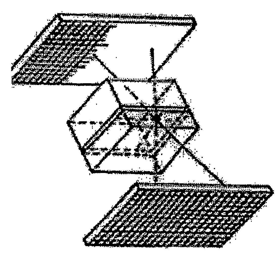
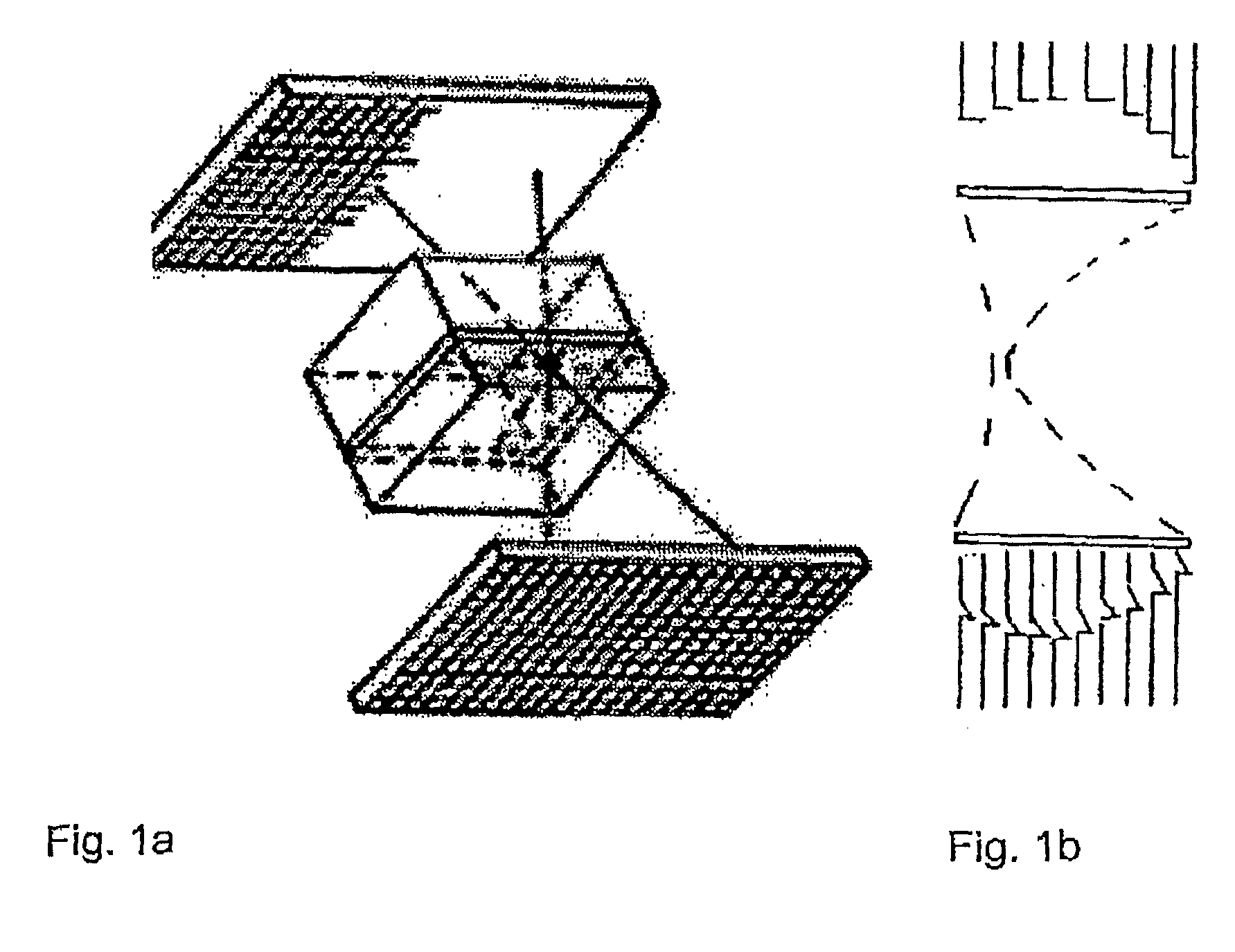
[0023]In the present invention, a Surface Topology Map (STM) reflects ultrasound waves from bone surfaces, such as the calcaneus, to determine spatial positions relative to ultrasound transducers at medial and lateral sides. The thickness of bone, delineated by the spacing between the two surfaces, is calculated from a position difference between the two surfaces. Importantly, corresponding surface points along a medial-lateral ultrasound wave pathway are unique with a spatial resolution of scan steps. The imaging QU...


PUM


Abstract

A surface topology map technique and apparatus are disclosed for determining calcaneus thickness for imaging quantitative ultrasound measurements; improving measurement accuracy, particularly in in vivo applications.

Description

PRIORITY[0001]This application claims priority to U.S. Provisional Application Ser. Nos. 60 / 791,642 and 60 / 791,644, both filed on Apr. 13, 2006.GOVERNMENT SUPPORT[0002]The invention was supported, in part, by NASA Cooperative Agreement NCC9-58, NIH R01 (AR49286), and National Space Biomedical Research Institute (TD00207 and TD00405). The U.S. Government has certain rights in the invention.BACKGROUND[0003]1. Field of the Invention[0004]Ultrasound imaging allows for noninvasive, nondestructive assessment, in a real-time manner, of material density and strength of hard tissue and irregular material, in an irregular working environment, i.e., complex three dimensional shapes, non-uniform internal structures and material properties, and, in particular, complex surface topology.[0005]2. Description of the Related Art[0006]Distance to an object can be measured by use of ultrasound. Ultrasound Velocity (UV) is a primary acoustic property that directly relates to bone quality evaluation. See...

Claims


Application Information

Patent Timeline
Patent Type & Authority Applications(United States)
IPC IPC(8): A61B8/00
CPCA61B5/103A61B8/0875A61B5/4504
Inventor QIN, YI-XIANXIA, YILIN, WEI
Owner RES FOUND OF STATE THE
Why Eureka
Try Eureka