Skeletal manipulation method

a skeletal system and manipulation technology, applied in the direction of prosthesis, invalid friendly device, therapy, etc., can solve the problems of increasing the difficulty of staples in clinical trials, realizing noticeable deformation, and rapid and severe curve progress, and achieve the effect of increasing the distraction for

a skeletal system and manipulation technology, applied in the direction of prosthesis, invalid friendly device, therapy, etc., can solve the problems of increasing the difficulty of staples in clinical trials, realizing noticeable deformation, and rapid and severe curve progress, and achieve the effect of increasing the distraction for

US20090112207A1Active Publication Date: 2009-04-30NUVASIVE SPECIALIZED ORTHOPEDICS INC

Image

  • Skeletal manipulation method
  • Skeletal manipulation method
  • Skeletal manipulation method

Examples


Embodiment Construction

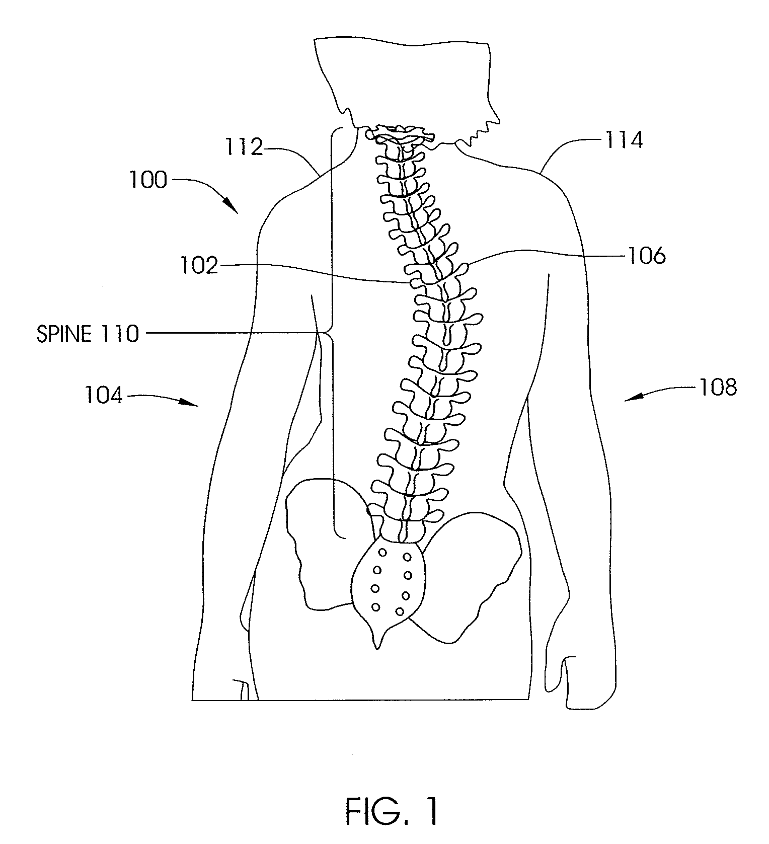
[0073]FIG. 1 illustrates a patient 100 with scoliosis. The concave portion 102 of the spinal curve can be seen on the left side 104 of the patient 100, and the convex portion 106 can be seen on the right side 108 of the patient 100. Of course, in other patients, the concave portion 102 may appear on the right side 108 of the patient 100 while the convex portion 106 may be found on the left side 104 of the patient. In addition, as seen in FIG. 1, some rotation of the spine 110 is present, and unevenness between the left shoulder 112 and right shoulder 114 is seen.

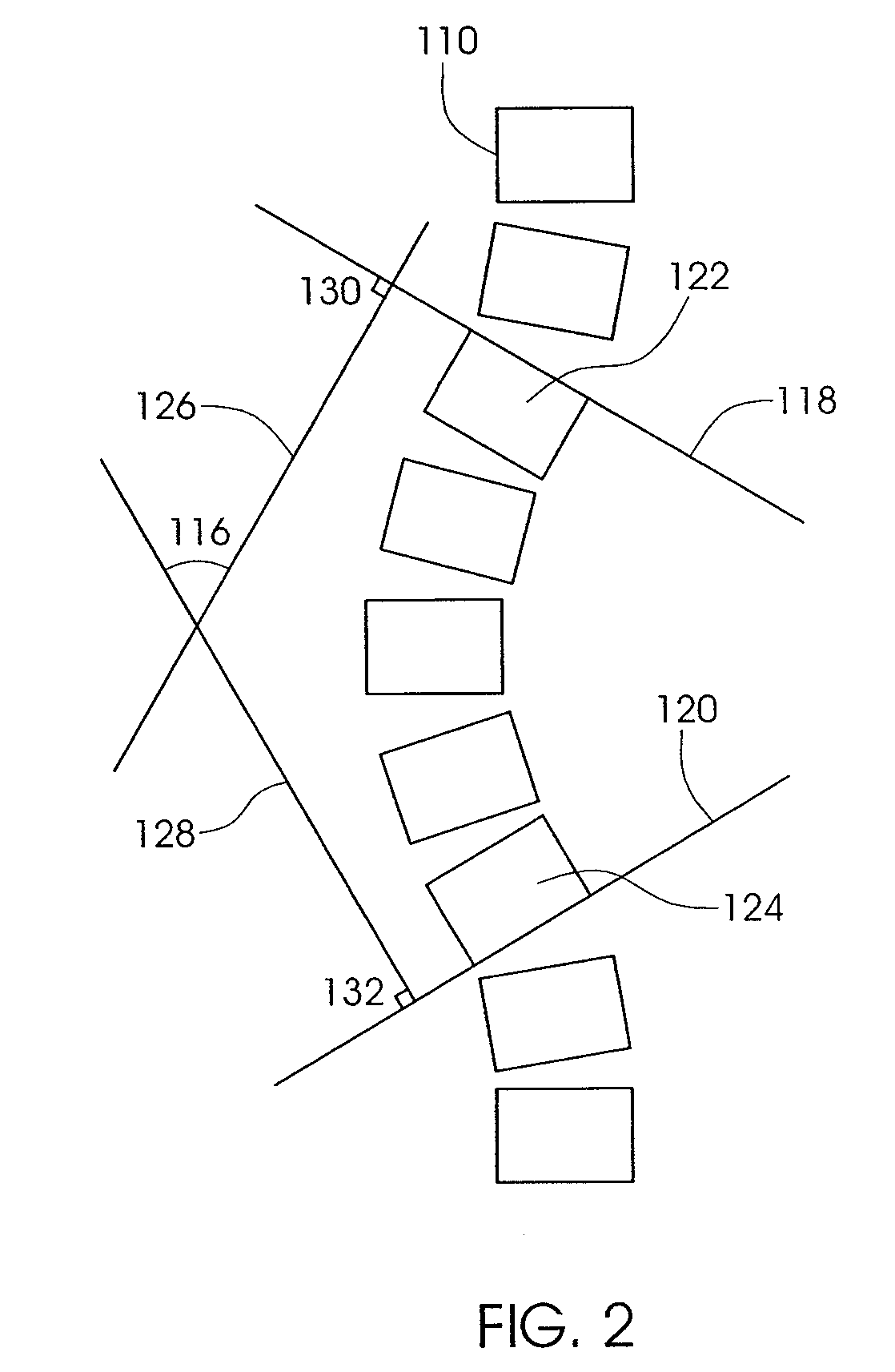
[0074]FIG. 2 illustrates the Cobb angle 116 of a spine 110 of a patient with scoliosis. To determine the Cobb angle, lines 118 and 120 are drawn from vertebra 122 and 124, respectively. Intersecting perpendicular lines 126 and 128 are drawn by creating 90° angles 130 and 132 from lines 118 and 120. The angle 116 created from the crossing of the perpendicular lines 126 and 128 is defined as the Cobb angle. In a perfectly stra...


PUM


Abstract

A method of treating scoliosis in a subject includes securing a scoliosis treatment device to first and second locations on the subject's skeletal system, the scoliosis treatment device including a first portion, a second portion moveably mounted relative to the first portion, and an adjustment device disposed on the device and configured to change a distraction force between the first location and the second location, the adjustment device including a rotationally mounted magnetic element configured to move the second portion relative to the first portion in response to rotation of the magnetic element. An external adjustment device is provided external to the subject and is able to adjust the distraction force between the first location and second location.

Description

RELATED APPLICATIONS[0001]This Application claims priority to U.S. Provisional Patent Application No. 60 / 983,917 filed on Oct. 30, 2007. The '917 Provisional Patent Application incorporated by reference as if set forth fully herein.FIELD OF THE INVENTION[0002]The field of the invention generally relates to medical devices for treating disorders of the skeletal system.BACKGROUND OF THE INVENTION[0003]Scoliosis is a general term for the sideways (lateral) curving of the spine, usually in the thoracic or thoracolumbar region. Scoliosis is commonly broken up into different treatment groups, Adolescent Idiopathic Scoliosis, Early Onset Scoliosis and Adult Scoliosis.[0004]Adolescent Idiopathic Scoliosis (AIS) typically affects children between ages 10 and 16, and becomes most severe during growth spurts that occur as the body is developing. One to two percent of children between ages 10 and 16 have some amount of scoliosis. Of every 1000 children, two to five develop curves that are serio...

Claims


Application Information

Patent Timeline
30 Apr 2009
Publication
US20090112207A1
IPC
A61B17/56; A61B19/00; A61B17/70; A61N2/00
CPC
A61B17/7016; A61B17/7044; A61B17/7065; A61B17/707; A61B17/88; A61B17/7266; A61B17/8004; A61B2017/00411
Inventors
WALKER, BLAIR; POOL, SCOTT