Manipulator

Active Publication Date: 2009-04-30
KARL STORZ GMBH & CO KG
View PDF10 Cites 122 Cited by
  • Summary
  • Abstract
  • Description
  • Claims
  • Application Information

AI Technical Summary

Benefits of technology

[0010]It is one of the objects of the present invention to provide a manipulator that has high degrees of freedom and

Problems solved by technology

The forceps that have been available heretofore, however, have few degrees of freedom, e.g., one degree of freedom, are difficult to handle because they are movable only in limited directions to grip and cut tissues and also to insert suture needles, and require surgeons to be skilled in using them.
However, external forces applied to the distal end working unit and gripping forces applied by the distal end working unit are not transmitted to the master side of the master-slave remote con

Method used


Image

  • Manipulator
  • Manipulator
  • Manipulator

Examples


first embodiment

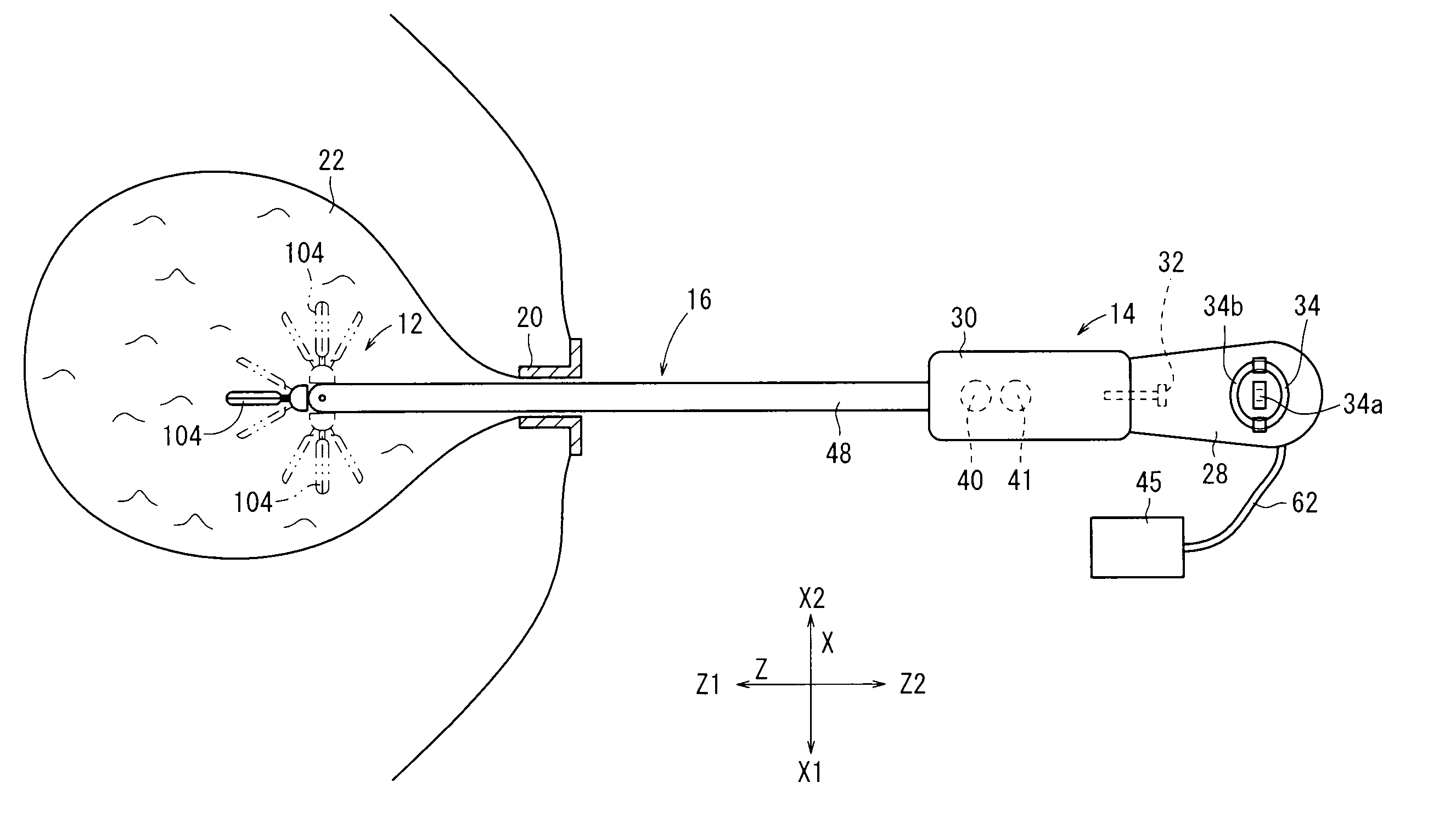
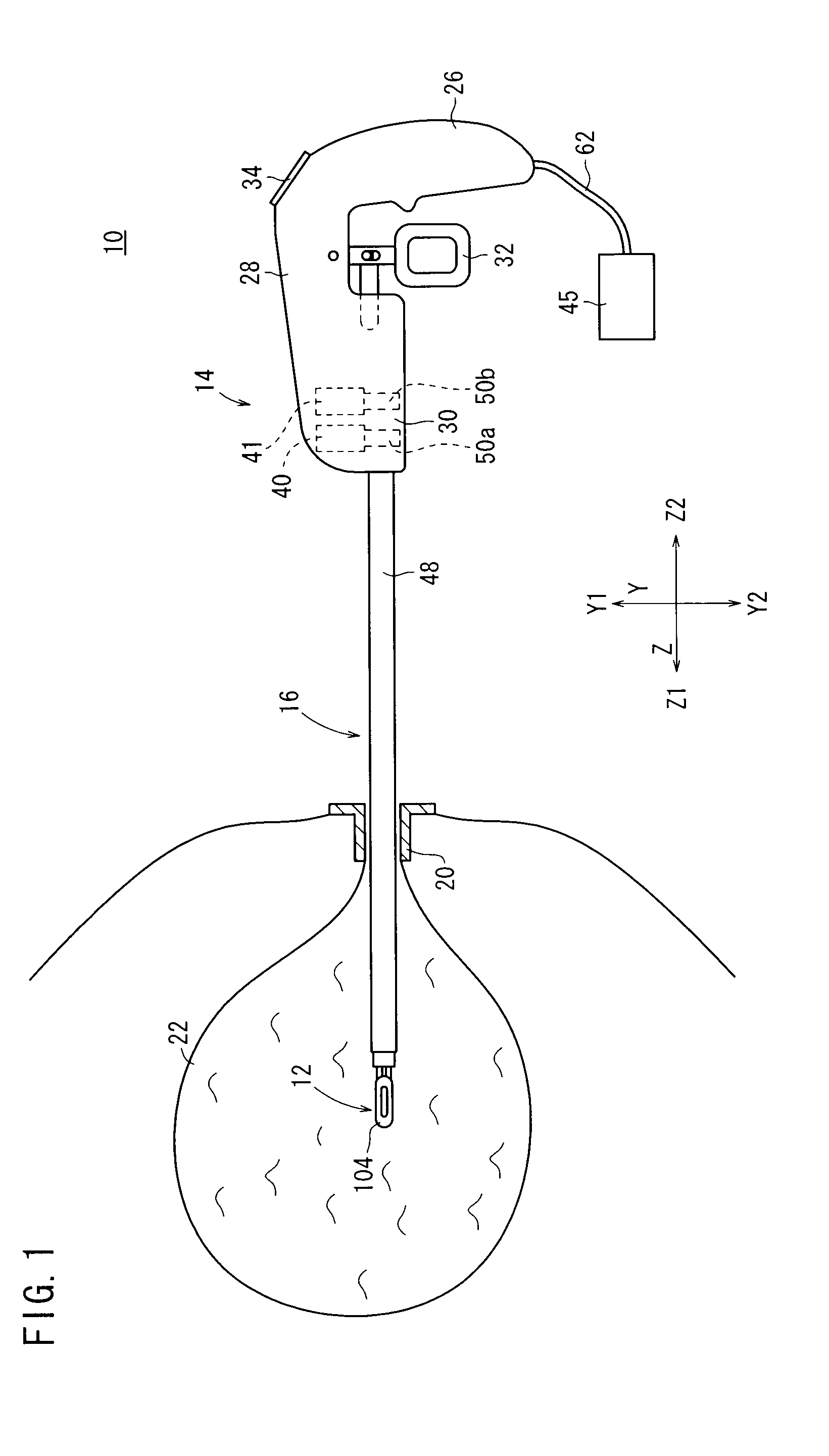
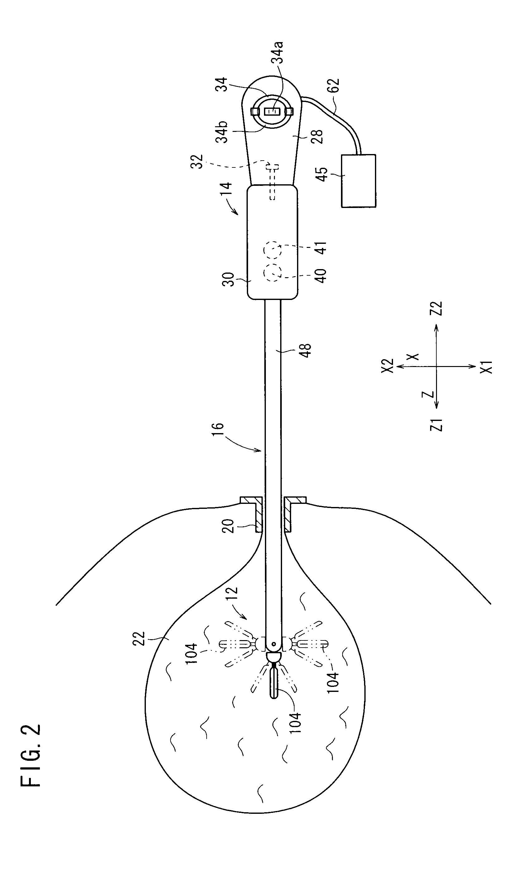
[0086]As shown in FIGS. 3, 4, 5, 6, and 7, the distal end working unit 12a comprises a wire-driven mechanism 100, a composite mechanism 102, and an end effector 104. The distal end working unit 12 incorporates therein mechanisms providing three degrees of freedom. These mechanisms include a mechanism having a first degree of freedom for angularly moving a portion of the distal end working unit 12 that is positioned ahead of a first rotational axis Oy extending along the Y direction, in a yawing direction about the first rotational axis Oy, a mechanism having a second degree of freedom for angularly moving the portion of the distal end working unit 12 in a rolling direction about a second rotational axis Or, and a mechanism having a third degree of freedom for opening and closing the end effector 104 on the distal end of the distal end working unit 12 about a third rotational axis Og.

[0087]The first rotational axis Oy of the mechanism having the first degree of freedom may be angula...

second embodiment

[0150]A distal end working unit 12b will be described below. Those parts of the distal end working unit 12b (as well as the distal end working units 12c through 12f) that are identical to those of the distal end working unit 12a shall be denoted by identical reference characters, and these features will not be described in detail below.

[0151]As shown in FIG. 18, the distal end working unit 12b is of a structure that is similar to the distal end working unit 12a, except that the idle pulley 140 (see FIG. 7) is dispensed with. In the distal end working unit 12b, the driven wire 252 is wound in one turn or more around the guide pulley 142 from two directions. Specifically, the driven wire 252 is wound around the first layer guide pulley 236 from the X2 direction, and is wound around the second layer guide pulley 238 from the X1 direction. The distal end working unit 12b operates in the same manner as the distal end working unit 12a. When the driven wire 252 is pulled in the Z2 directi...

third embodiment

[0154]The distal end working unit 12c will be described below.

[0155]As shown in FIG. 19, the distal end working unit 12c is different from the distal end working unit 12a in terms of the structure of the end effector 104.

[0156]The distal end working unit 12c includes an end effector 300 having a double-sided-open type structure, with a pair of grippers 302 being movable thereon. The end effector 300 comprises a gripper base 304 integrally combined with the cover 160, a pair of end effector members 308 movable about a pin 196 mounted on the gripper base 304, and a pair of gripper links 220.

[0157]Each of the end effector members 308 has an L shape, similar to the second end effector member 192, and comprises a gripper 302 extending in the Z1 direction and a lever 310 bent about 35° and extending from the gripper 302. The L-shaped bent corner includes a hole 216 formed therein, and the pin 196 is inserted into the hole 216, so that the end effector members 308 are swingable about the ...


PUM


Abstract

A manipulator includes a wire which is movable back and forth, a driven wire both ends of which are connected to the wire, an idle pulley, a guide pulley, a driven pulley which is movable back and forth, and an end effector coupled to the driven pulley. The driven wire passes from a terminal along a first side on the idle pulley and extends to a second side opposite to the first side, and then passes along the second side on the driven pulley. The driven wire is then wound around the driven pulley and passes along the first side on the driven pulley and then the second side on the idle pulley, and finally returns to the terminal, thereby making up an 8-shaped configuration path. The driven wire is crossed between the idle pulley and the guide pulley.

Description

BACKGROUND OF THE INVENTION[0001]1. Field of the Invention[0002]The present invention relates to a manipulator having a distal end working unit which includes an end effector.[0003]2. Description of the Related Art[0004]According to a laparoscopic surgical operation process, some small holes are opened in the abdominal region, for example, of a patient and an endoscope and manipulators or forceps are inserted into the holes. The surgeon performs a surgical operation on the patient with the manipulators or forceps while watching an image captured by the endoscope and displayed on a display monitor. Since the laparoscopic surgical operation process does not require a laparotomy, it is less burdensome on the patient and greatly reduces the number of days required for the patient to spend before recovering from the operation or being released from the hospital, it is expected to increase a range of surgical operations to which it is applicable.[0005]Manipulators for laparoscopic surgica...

Claims


Application Information

Patent Timeline
IPC IPC(8): A61B17/29A61B17/00
CPCA61B18/1445A61B19/22A61B2017/2927B25J9/104A61B2017/2939A61B2019/2242A61B2019/2276A61B2017/2932A61B2034/742A61B34/70A61B34/71
Inventor JINNO, MAKOTO
Owner KARL STORZ GMBH & CO KG
Why Eureka
Try Eureka