Stent segments axially connected by thin film

a thin film and axial connection technology, applied in the field of expandable intraluminal grafts, can solve the problems of prior art stent collapse and functional limitations of prior art stents, and achieve the effects of reducing the risk of stent collaps

Active Publication Date: 2009-04-30
VACTRONIX SCI LLC
View PDF76 Cites 110 Cited by
  • Summary
  • Abstract
  • Description
  • Claims
  • Application Information

AI Technical Summary

Benefits of technology

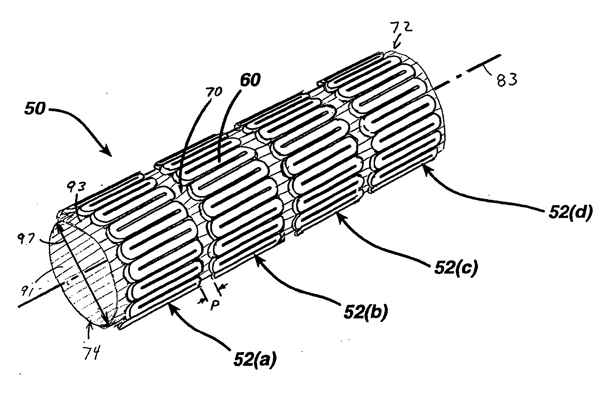
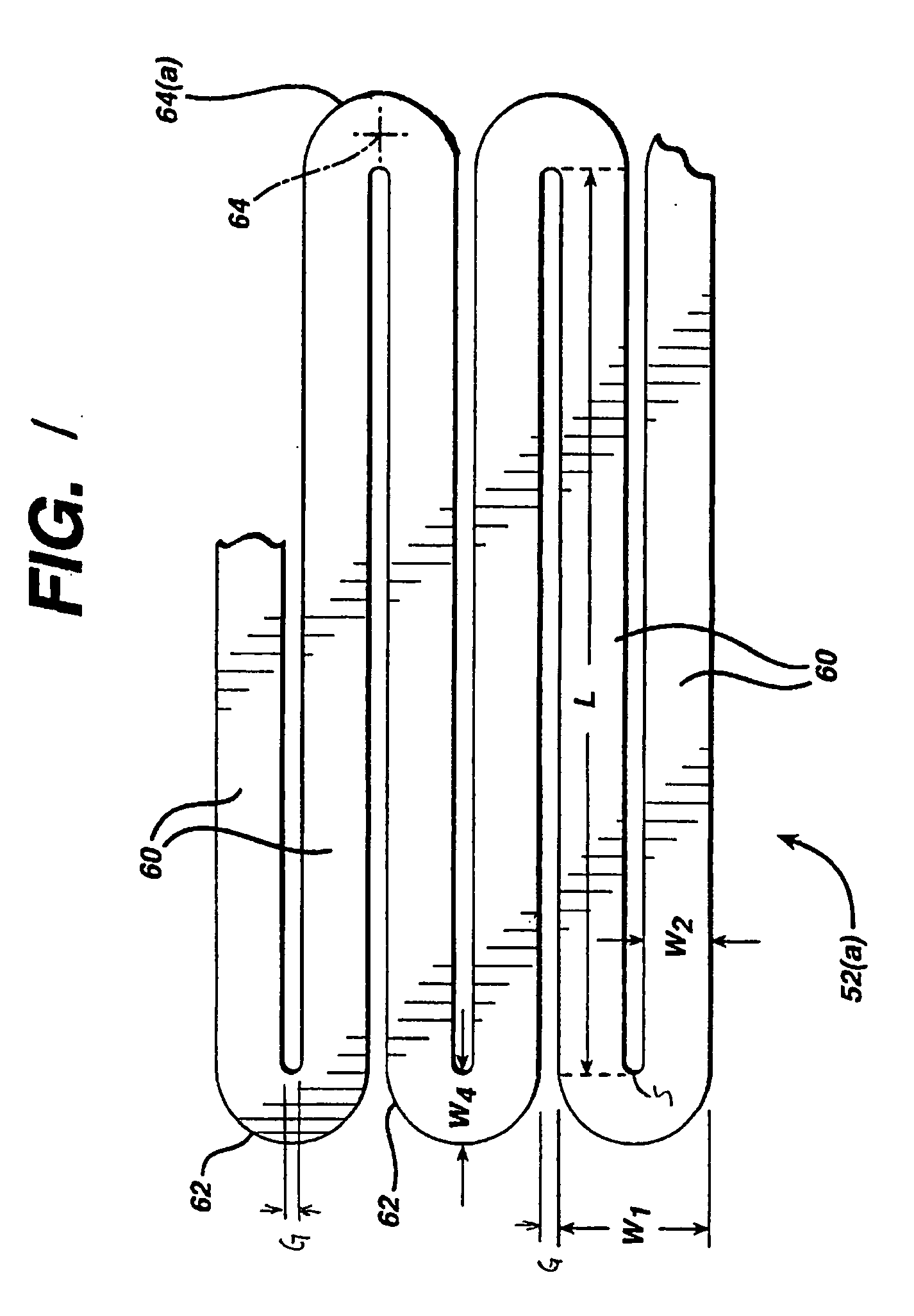
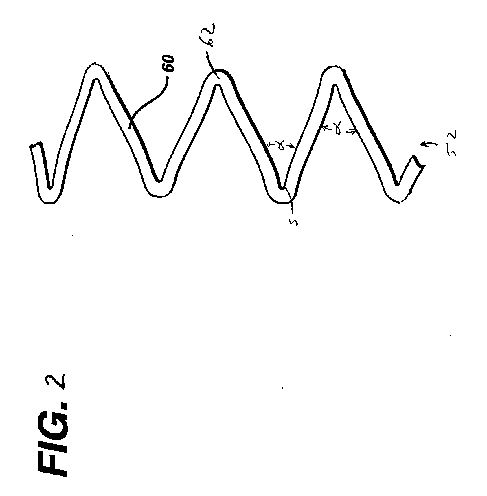
[0005]The present invention is an improved stent has good radial strength to hold the vessel open and greater flexibility that is suitable for implantation in more sharply bent vessels. The inventive stent includes a thin film tube that is attached to a plurality of hoops axially aligned between the front and back ends of the stent. Each of the hoops includes a plurality of longitudinal struts and a plurality of loops connecting adjacent struts. The struts and loops form a continuous serpentine pattern around the diameter of the hoop. The thin film tube holds the hoops together and also provide a space between the adjacent hoops. The stent has a compressed diameter for simplified implantation into the patient and an expanded diameter that is assumed after it is inserted into the patient. The inventive stent is a tubular member that has front and back open ends and a longitudinal axis extending therebetween.
[0006]The inventive stent has improved flexibility because the adjacent hoops are held together with a flexible thin film tube rather than bridges. The thin film tube is more flexible than the bridges because the thin film tube is much thinner. The thin film spans the area between the adjacent hoops and can easily fold when compressed. This improved flexibility allows the stent to be easily moved through blood vessels and deployed in a bent vessel within the patient. In contrast, the more rigid bridges that couple the adjacent hoops restrict the bending radius of the prior art stents.
[0008]In a preferred embodiment, the thin film tube and hoops are made of a super elastic metal alloy that can change from the martensitic molecular phase to the austenitic phase by changing the stent temperature. For implantation, the stent is compressed and loaded onto a delivery tube apparatus. The delivery device holds the stent in the compressed state and is used to transport the stent to a specific area within a patient. The stent is deployed at a damaged area of the blood vessel by releasing the stent from the delivery apparatus. In an embodiment, the delivery device pushes the stent out of the delivery tube while simultaneously pulling the delivery tube back to expose the stent. This allows the inventive stent to expand radially to the inner diameter of the blood vessel without any axial movement relative to the vessel. The expanded stent remains axially stationary relative to the blood vessel to avoid damage during the deployment process.
[0009]The stent may have radio opaque markers which allow the surgeons to monitor the location for the stent during the delivery procedure. By watching the position of the stent within the patient, the stent can be positioned within the vessel more accurately. The radio opaque markers can be attached to the stent by welding the markers to the stent. Alternatively, the markers may be attached with adhesives, mechanical fasteners or other coupling systems.

Problems solved by technology

Prior art stents have some functional limitations due to their current design.
For example, the prior art stent can collapse when it is bent around a sharp angle.

Method used


Image

  • Stent segments axially connected by thin film
  • Stent segments axially connected by thin film
  • Stent segments axially connected by thin film

Examples


first embodiment

[0040]In a first embodiment shown in FIG. 3, all of the hoops 52(a)-52(d) are attached to the outer surface 93 of thin film tube 70. The hoops 52(a)-52(d) are uniform in size and may be welded or adhesively bonded to the outer surface of the thin film tube. The hoops 52(a)-52(d) are equally spaced apart from each other along the length of the thin film tube 70. The spacing P of the hoops 52(a)-52(d) affects the stiffness of the stent 50. The stent 50 will be stiffer if the hoops 52(a)-52(d) are placed very close to each other on the thin film tube, rather than spaced farther apart.

second embodiment

[0041]In a second embodiment shown in FIG. 4, a stent is shown with the hoops 52(a)-52(d) attached to the inner surface 91 of the thin film tube 70. In this embodiment, the hoops 52(a)-52(d) are concealed from view by the thin film tube 70. For clarity, the thin film tube 70 is shown as partially covering hoop 52(d) and completely removed from hoops 52(a)-52(c). The thin film tube 70 provides a smooth outer surface for the stent 50 and may reduce the friction of the stent 50 as it is deployed or retracted through a tubular delivery device.

third embodiment

[0042]In a third embodiment shown in FIG. 5, the hoops 52(a)-52(d) are arranged in an alternating pattern along the length of the thin film tube 70. Hoops 52(a) and 52(c) are attached to the outer surface 93 while the adjacent hoops 52(b) and 52(d) are attached to the inner surface 91 of the thin film tube 70. This alternating pattern of hoops 52 coupled to the inner and outer surfaces of the thin tube 70 may continue along the length of the stent 50. In the compressed state the hoops 52(a) and 52(c) attached to the outer surface 93 of the thin film tube 70 may have a larger diameter than the hoops 52(b) and 52(d) which are attached to the inner surface 91. The thin film tube 70 may have a uniform diameter and thickness along the axial length. In other embodiments, the stent may have an arrangement of hoops that are attached to the inner and outer surfaces of the thin film tube in any pattern. For example, the stent may have pattern that includes one or more adjacent hoops mounted o...


PUM

PropertyMeasurementUnit
thicknessaaaaaaaaaa
thicknessaaaaaaaaaa
angleaaaaaaaaaa

Abstract

In accordance with the present invention, there is provided a stent for insertion into a vessel of a patient. The stent has a front and back open ends and a longitudinal axis extending therebetween. The stent has a plurality of adjacent hoops that are held in alignment with the longitudinal axis between the front and back open ends by a thin film tube. The hoops are attached to either the inner or outer surface of the thin film tube. The stent is compressed into a first smaller diameter for insertion into the vessel with a delivery tube and a second larger diameter for deployment into the vessel. The inventive stent can be retracted into the delivery tube if it is improperly deployed.

Description

FIELD OF THE INVENTION[0001]The present invention relates to an expandable intraluminal grafts (“stents”) for use within a body passageway or duct which are particularly useful for repairing blood vessels that have been narrowed or occluded by disease. The present invention relates even further to such stents which are self-expanding and made from a super elastic material such as Nitinol.BACKGROUND OF THE INVENTION BACKGROUND[0002]Percutaneous transluminal coronary angioplasty (PTCA) is a therapeutic medical procedure used to increase blood flow through the coronary artery and can often be used as an alternative to coronary by-pass surgery. In this procedure, the angioplasty balloon is inflated within the stenosed vessel in order to disrupt the wall components of the vessel to obtain an enlarged lumen. With respect to arterial stenosed lesions, the relatively incompressible plaque remains unaltered, while the more elastic medial and adventitial layers of the body passageway stretch ...

Claims


Application Information

Patent Timeline
Patent Type & Authority Applications(United States)
IPC IPC(8): A61F2/82B23P13/04
CPCA61F2/07A61F2/844A61F2/91A61F2/915A61F2002/072Y10T29/49995A61F2250/0023A61F2/89A61F2220/005A61F2220/0058Y10T29/49982A61F2002/075
Inventor BONSIGNORE, CRAIGRICE, CAROLYN
Owner VACTRONIX SCI LLC
Why Eureka
Try Eureka