Memory-Based High-Speed Interferometer

Inactive Publication Date: 2009-04-30
MITSUBISHI ELECTRIC RES LAB INC
View PDF4 Cites 3 Cited by
  • Summary
  • Abstract
  • Description
  • Claims
  • Application Information

AI Technical Summary

Problems solved by technology

Unfortunately, the resolution of an interferometer of this form is one quarter of a wavelength of path difference; in the case of a typical interferometer using a helium-neon (HeNe) laser that wavelength is fixed by the physics of helium and neon at 632.818 nanometers and cannot be changed.
The disadvantages of the conventional methods are that the two parts of the readout are of different types: the number of quarter-wavelengths is read out by quadrature encoding in real time, while the fraction of the wavelength is the result of a software interpolation which is delayed by some amount of time.
Prior art interferometers are severely limited in their speed, typically in the range of about 20 K Hz, and often much less.
Changing the operation of the interferometer in real-time is impossible in most cases.

Method used


Image

  • Memory-Based High-Speed Interferometer
  • Memory-Based High-Speed Interferometer
  • Memory-Based High-Speed Interferometer

Examples


Embodiment Construction

Interferometry

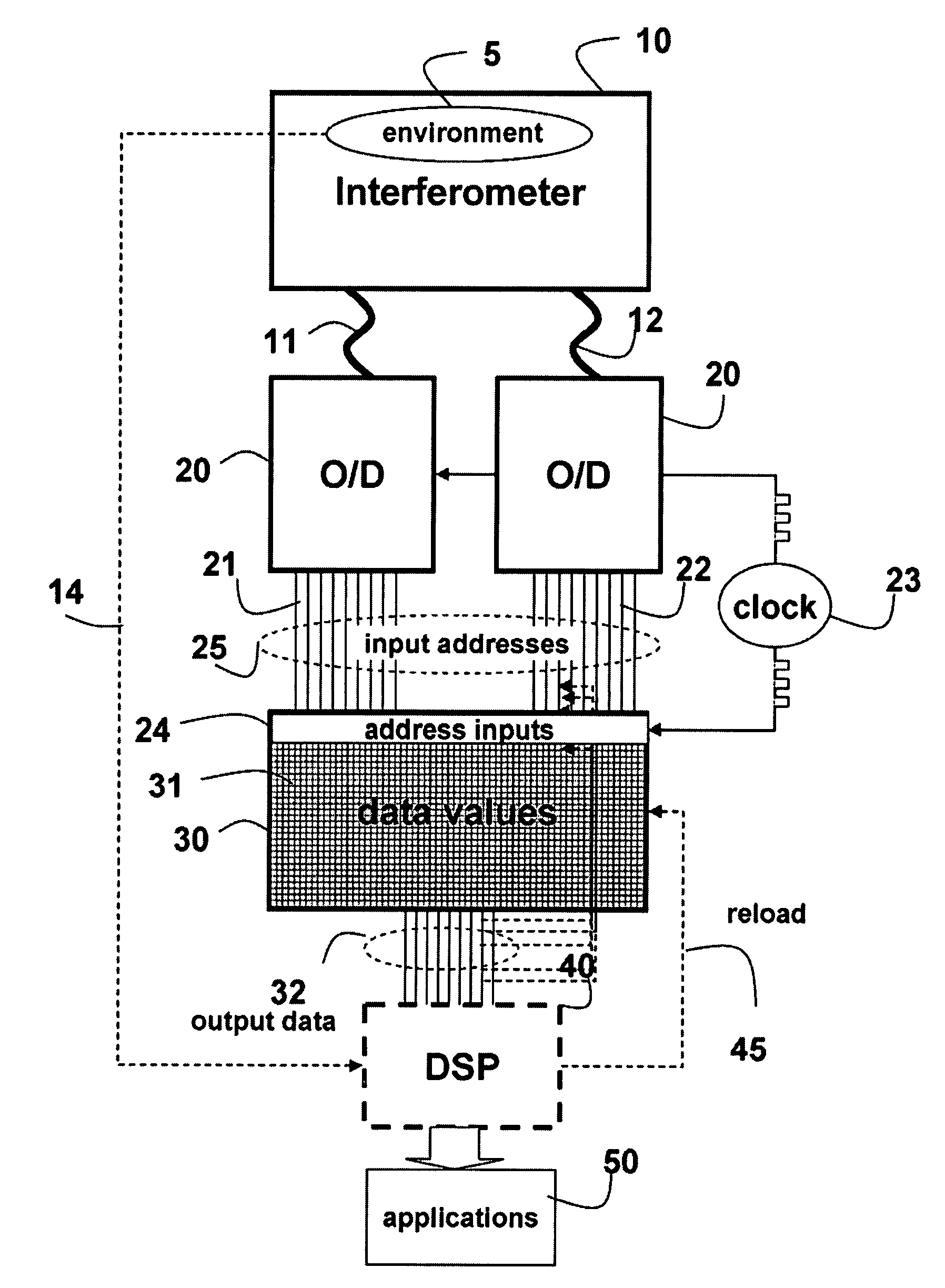
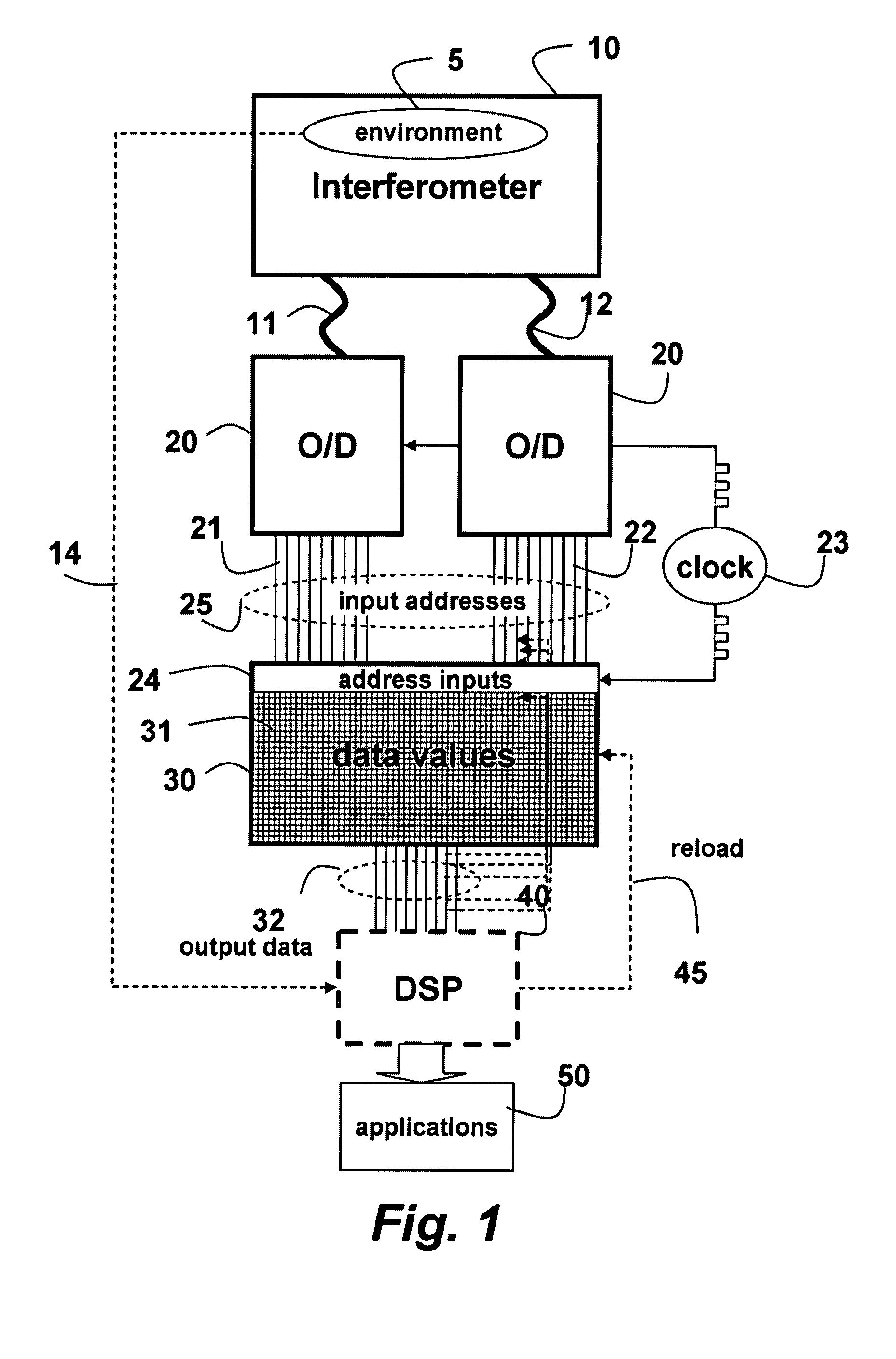
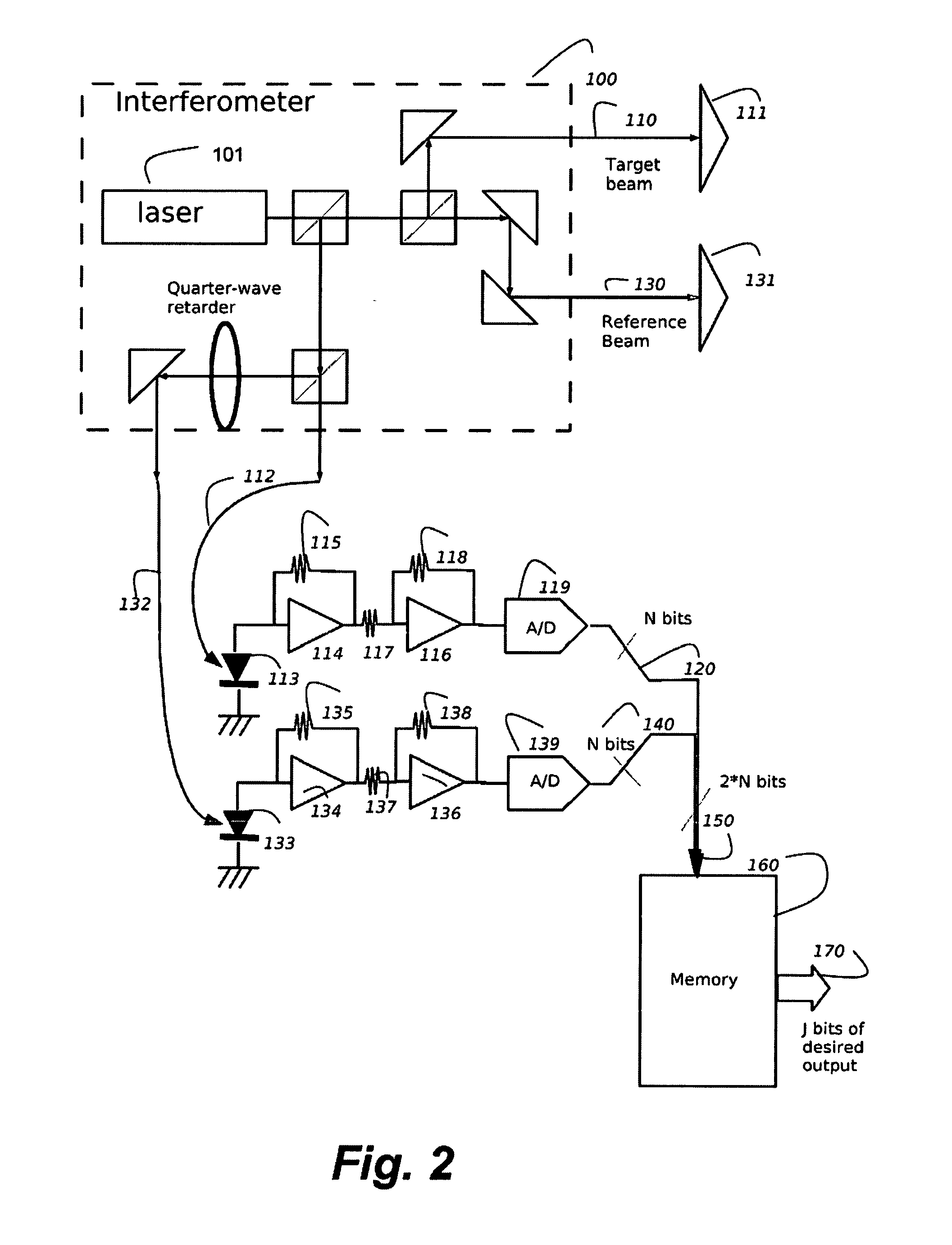
[0019]Our invention comprises a Michelson-style quadrature laser interferometer with a conventional optical configuration, with the addition of photodiodes, amplifiers, A / D converters and memory. The A / D converters change intensities of the interfering optical signals to digital signals in a form of memory addresses.

[0020]Direct Access Memory

[0021]Accessing the memory directly converts the amplitude (intensities) of the two quadrature-encoded interferometer beam signals into any desired quadrature encoded positional signal. The high-speed path, after the A / D converters, does not include any software or electronic devices with long latencies. Of course, the down-stream processing of the data read from the memory can use software, and software can be used to configure the system or update the content of the memory during operation, but those operations do not impinge on the high-speed measurement path.

[0022]One embodiment of our invention uses the results of the A / D conv...


PUM


Abstract

An interferometer produces a first optical signal and a second optical signal interfering with each other. The optical signals are converted digital signals form addresses. A memory stores data values corresponding to the first and second optical signals, and in which the addresses are used to directly read the data values stored at the addresses. The data values stored in the memory can be dynamically adapting while converting the first and second optical signals and reading the data values.

Description

FIELD OF THE INVENTION[0001]The present invention relates generally to optical measurement devices, and more particularly to high-speed optical interferometers.BACKGROUND OF THE INVENTION[0002]Interferometry superposes (interferes) two or more (electro-magnetic) waves, to detect differences between the waves, i.e., their interfering characteristics. The most common interferometer is the Michelson type of interferometer. The basic components of the Michelson interferometer are a light source, a detector, two mirrors and one semitransparent mirror, often called a beam splitter.[0003]A simple interferometer counts the “fringes” where the intensity of the output wave runs in a complete cycle from maximum (where the waves constructively interfere) to a minimum (complete destructive interference) and back to a maximum again. These intensities are sine waves. Because of this single output, a simple interferometer can detect a change of differential distance in the path of the wave, but not...

Claims


Application Information

Patent Timeline
IPC IPC(8): G01R13/00G01R15/00
CPCG01B9/02088G01B9/02081G01J9/02
Inventor YERAZUNIS, WILLIAM S.BRINKMAN, DIRK
Owner MITSUBISHI ELECTRIC RES LAB INC
Why Eureka
Try Eureka