Managing the tracing of the execution of a computer program

Inactive Publication Date: 2009-04-30
IBM CORP
View PDF1 Cites 43 Cited by
  • Summary
  • Abstract
  • Description
  • Claims
  • Application Information

AI Technical Summary

Benefits of technology

[0016]Where, as in all current data processing systems, there is a Memory Management Unit (MMU) which controls the copying of data to and from the main memory, it is a further feature of the invention that the MMU is arranged to copy logically as

Problems solved by technology

Because tracing program execution requires a great deal of computer time and storage, the default situation during normal program execution is that the trace facility is disabled.
When, however, the trace facility is enabled, various techniques have been used to limit the impact on performance.
However, the actual tracing may still be very time consuming, particularly if the dat

Method used


Image

  • Managing the tracing of the execution of a computer program
  • Managing the tracing of the execution of a computer program
  • Managing the tracing of the execution of a computer program

Examples


Embodiment Construction

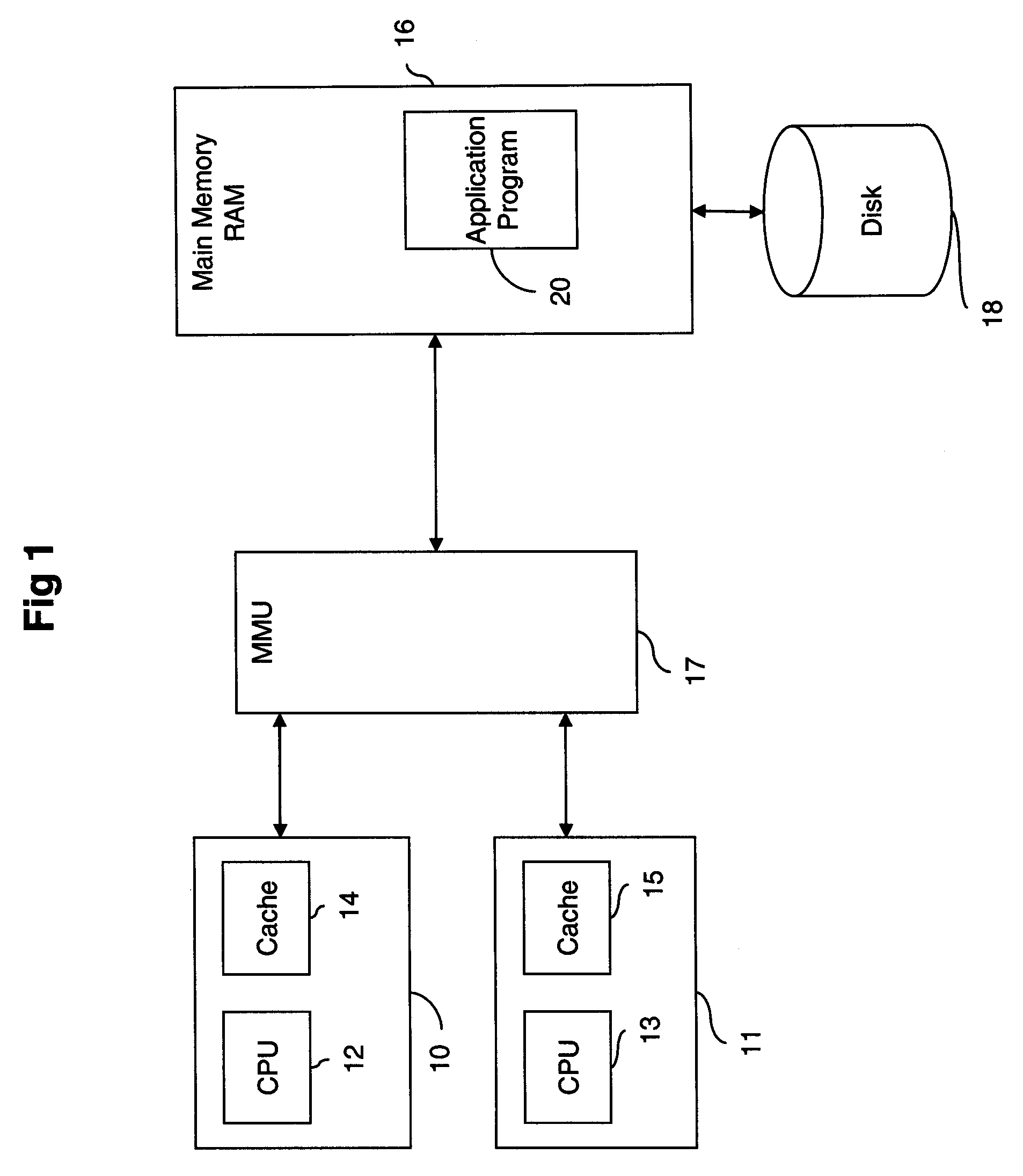
[0027]The data processing system of FIG. 1, in which one embodiment of the invention can be implemented, comprises two parallel processors 10 and 11, consisting of central processing units (CPUs) 12 and 13 having respective caches 14 and 15. Although not explicitly shown in the drawing, each cache consists of computer memory and a cache controller to manage the use of said memory. These communicate with volatile main memory RAM 16, via a shared Memory Management Unit (MMU) 17. In turn, the main memory 16 is linked, via a storage control unit (not shown) to non-volatile storage in the shape of hard disk file 18. There is no particular significance in the choice of a parallel processor system, and embodiments of the invention would work equally well with a single processor.

[0028]The MMU performs the conventional functions of controlling the copying of data to and from main memory 16 via the caches. The MMU has two basic functions: “Store” and “Load”. The Load function writes or copies...


PUM


Abstract

A method and system for the management of tracing data of interest in a data processing system comprises identifying the location and length of one or more such units of interest as each unit is stored in main memory during execution of the program and recording a logical assignment of each unit of interest to a slot in a wrap around trace buffer. Copying of the units of interest to the trace buffer is deferred unless one or more predefined events occur. Such events may include an attempt to overwrite the data which has been logically assigned or a request for information stored in the trace buffer. The recorded assignments are discarded whenever it is calculated that the capacity of the trace buffer would be exceeded resulting in the corresponding units never needing to be copied to the trace buffer.

Description

CROSS-REFERENCE TO RELATED APPLICATIONS[0001]This application claims priority to United Kingdom Patent Application No. 07119273.6, filed Oct. 25, 2007, the contents of which are incorporated herein by reference in its entirety.FIELD OF THE INVENTION[0002]The present invention relates to the management of the tracing of data generated sequentially during execution of a computer program in a data processing system.BACKGROUND OF THE INVENTION[0003]It is a well known requirement in the field of computer programming to be able to trace the execution path of a program by the recording of key data and events. The main reason for doing this is to be able to analyse the reasons for program failure by examining the recorded trace data. Alternatively, it might be required to analyse the performance of a program. Although tracing can, in some cases, be of direct assistance to end user customers it is primarily needed by customer support staff to assist their customers and also by the programmin...

Claims


Application Information

Patent Timeline
IPC IPC(8): G06F9/44
CPCG06F11/3409G06F2201/885G06F2201/86G06F11/3476
Inventor BIRKILL, ALEXISBLUE, GEORGE MELDRUMWILLOUGHBY, PHILIP GRAHAM
Owner IBM CORP
Why Eureka
Try Eureka