
Windshield wiper airfoil device

a technology of airfoil and windshield wiper, which is applied in the direction of vehicle maintenance, vehicle cleaning, domestic applications, etc., can solve the problems of limited visibility of the driver and potentially dangerous situations not only for the driver of the vehicle but for other motorists, and achieves convenient assembly, high speed, and easy manufacturing

Inactive Publication Date: 2009-05-07
LUCKER DAVID A
View PDF9 Cites 2 Cited by
  • Summary
  • Abstract
  • Description
  • Claims
  • Application Information

AI Technical Summary

Benefits of technology

[0004]It is, therefore, one of the primary objects of the present invention to provide an airfoil device attachable to the superstructure of a windshield wiper blade assembly that helps prevent the flexible blade of such assembly from lifting off the windshield while driving at a high rate of speed.
[0006]Still another object of the present invention is to provide an airfoil device that is generally easy to manufacture.

Problems solved by technology

However, when the vehicle is traveling at a high rate of speed, airflow moving across the windshield can cause portions of the flexible blade to lift, leading to limited visibility for the driver.
This is a potentially dangerous situation not only for the driver of the vehicle but to other motorists and / or pedestrians in the vicinity as well.

Method used


Image

  • Windshield wiper airfoil device
  • Windshield wiper airfoil device

Examples


Embodiment Construction

, particularly, when such description is taken in conjunction with the attached drawing figures and with the appended claims.

BRIEF DESCRIPTION OF THE DRAWINGS

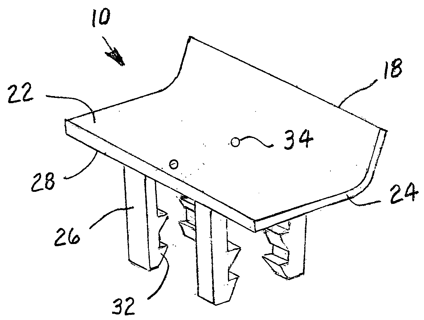
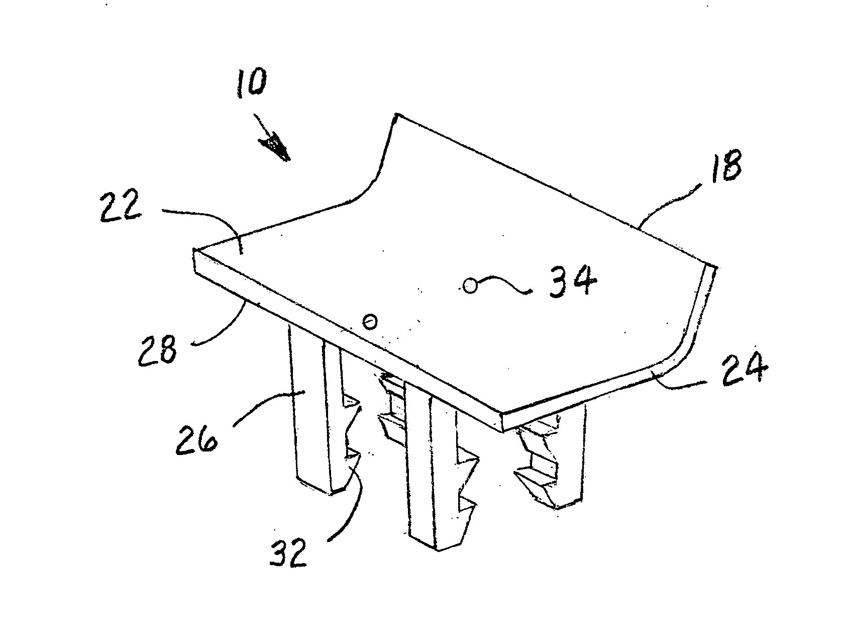
[0009]FIG. 1 is a perspective view of a presently preferred embodiment of an airfoil device to be attached to a windshield wiper blade assembly on a vehicle to maintain the wiper blade in contact with such windshield while driving at a relatively high rate of speed; and

[0010]FIG. 2 is a perspective view of the airfoil device illustrated in FIG. 1 as it is attached to the windshield wiper blade assembly.

DETAILED DESCRIPTION OF A PRESENTLY PREFERRED AND VARIOUS ALTERNATIVE EMBODIMENTS OF THE INVENTION

[0011]Prior to proceeding to the more detailed description of the present invention it should be noted that, for the sake of clarity and understanding, identical components which have identical functions have been identified with identical reference numerals throughout the several views illustrated in the drawing figures.

[0012]Refere...


PUM


Abstract

A device that attaches to a predetermined portion of a pressure distributing superstructure of a windshield wiper blade assembly on a vehicle for preventing a flexible blade of the assembly from lifting off the windshield of the vehicle when it is traveling at a relatively high speed. The device includes an airfoil member having a substantially flat first portion and a laterally extending substantially concave second portion for deflecting high speed airflow and producing an aerodynamic force downward onto the superstructure pushing the blade against the windshield. There are a pre-selected number of elongated clip members that are affixed to a bottom surface of the first portion of the airfoil member, each including at least one protruding portion that is engageable with the superstructure of the assembly for clipping the airfoil member thereon.

Description

FIELD OF THE INVENTION[0001]The present invention relates, in general, to windshield wiper blade assemblies and, more particularly, the invention relates to an airfoil device that can be attached to a predetermined portion of the superstructure of a windshield wiper blade assembly on a vehicle for preventing the flexible blade of such assembly from lifting off the windshield when the vehicle is traveling at high speed.BACKGROUND OF THE INVENTION[0002]Windshield wiper blade assemblies have been in existence many years prior to the conception and development of the present invention, as is generally well known in the prior art. These assemblies are designed to clear precipitation, such as rain, sleet, snow, etc., off the windshield of a vehicle allowing better visibility for the driver of the vehicle in inclement weather conditions. However, when the vehicle is traveling at a high rate of speed, airflow moving across the windshield can cause portions of the flexible blade to lift, lea...

Claims


Application Information

Patent Timeline
Patent Type & Authority Applications(United States)
IPC IPC(8): B60S1/02
CPCB60S1/3806B60S1/0408
Inventor LUCKER, DAVID A.
Owner LUCKER DAVID A
Learn More